Air-cooled engine

An air-cooled engine and engine technology, which is applied to engine components, engine cooling, machine/engine, etc., can solve problems such as complex metal mold structures, and achieve improved cooling effects and improved cooling effects

Active Publication Date: 2008-07-30
HONDA MOTOR CO LTD
View PDF2 Cites 3 Cited by
  • Summary
  • Abstract
  • Description
  • Claims
  • Application Information

AI Technical Summary

Problems solved by technology

However, with this method, the structure of the metal mold becom

Method used


Image

  • Air-cooled engine
  • Air-cooled engine
  • Air-cooled engine

Examples


Embodiment Construction

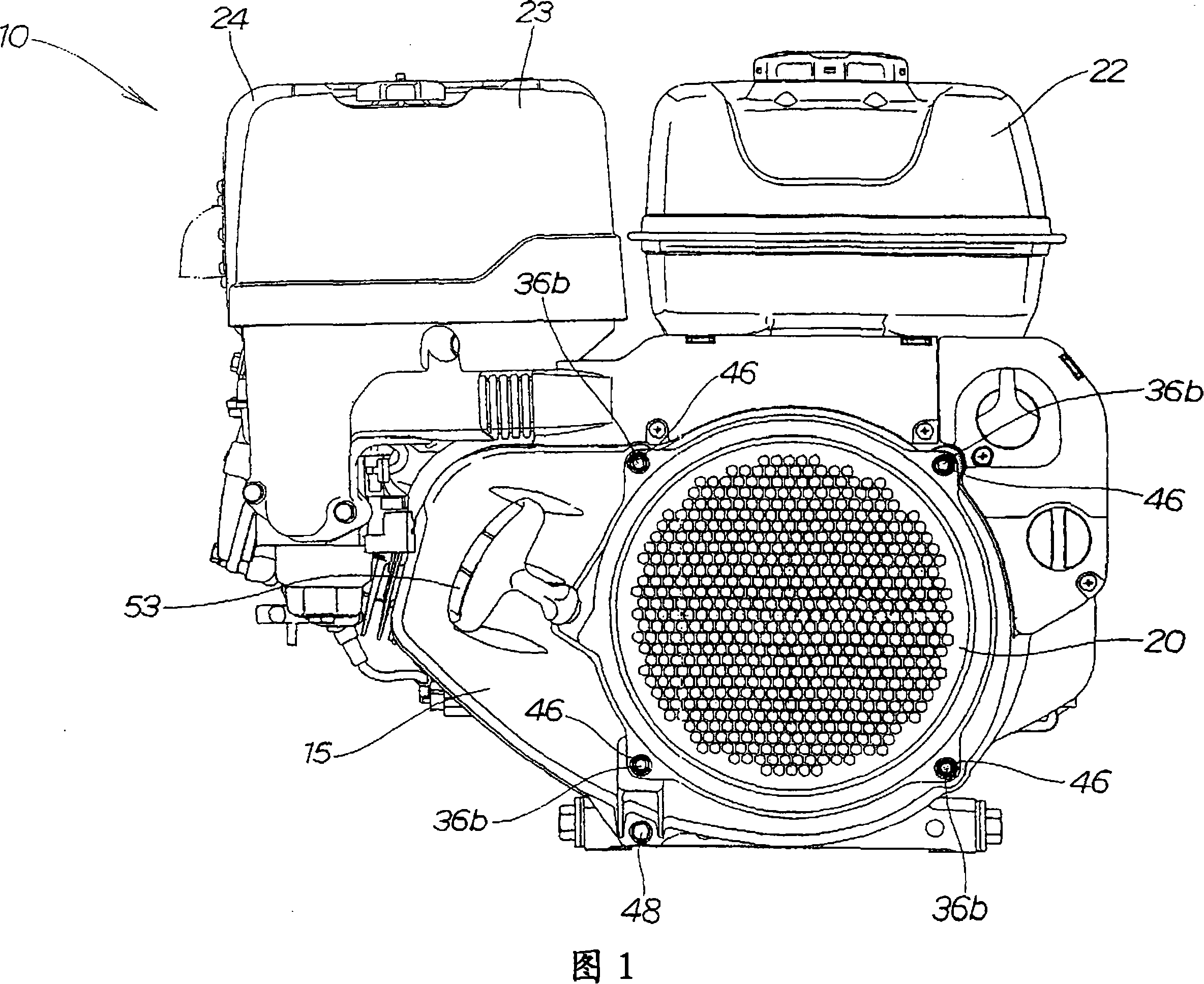
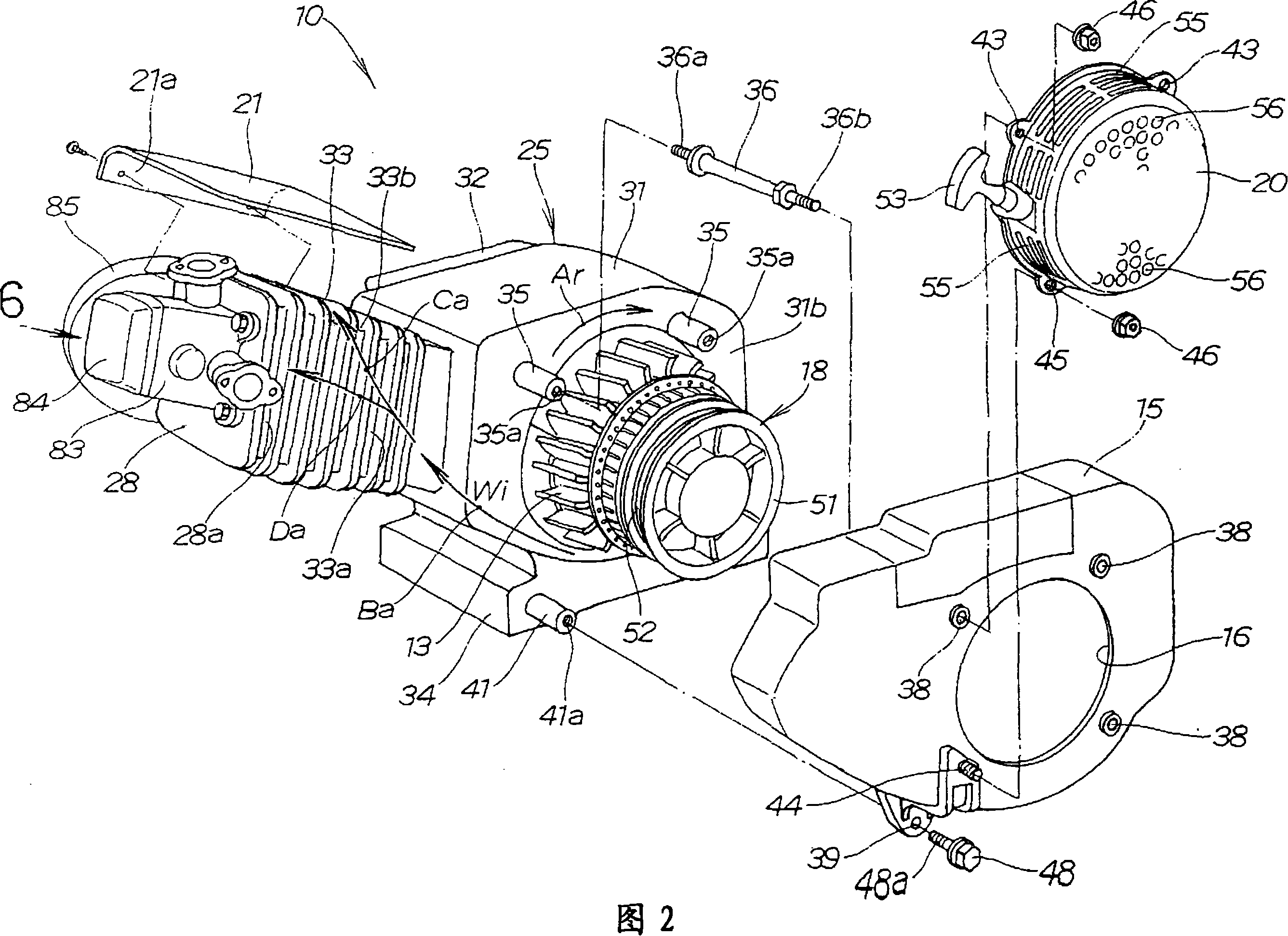
[0044]As shown in Figures 1 and 2, the air-cooled engine 10 includes a cooling fan 13, a fan cover 15 covering the cooling fan 13, a recoil starter 18, a starter cover 20 covering the recoil starter 18, and a fuel tank 22 , air filter 23 and muffler 24.

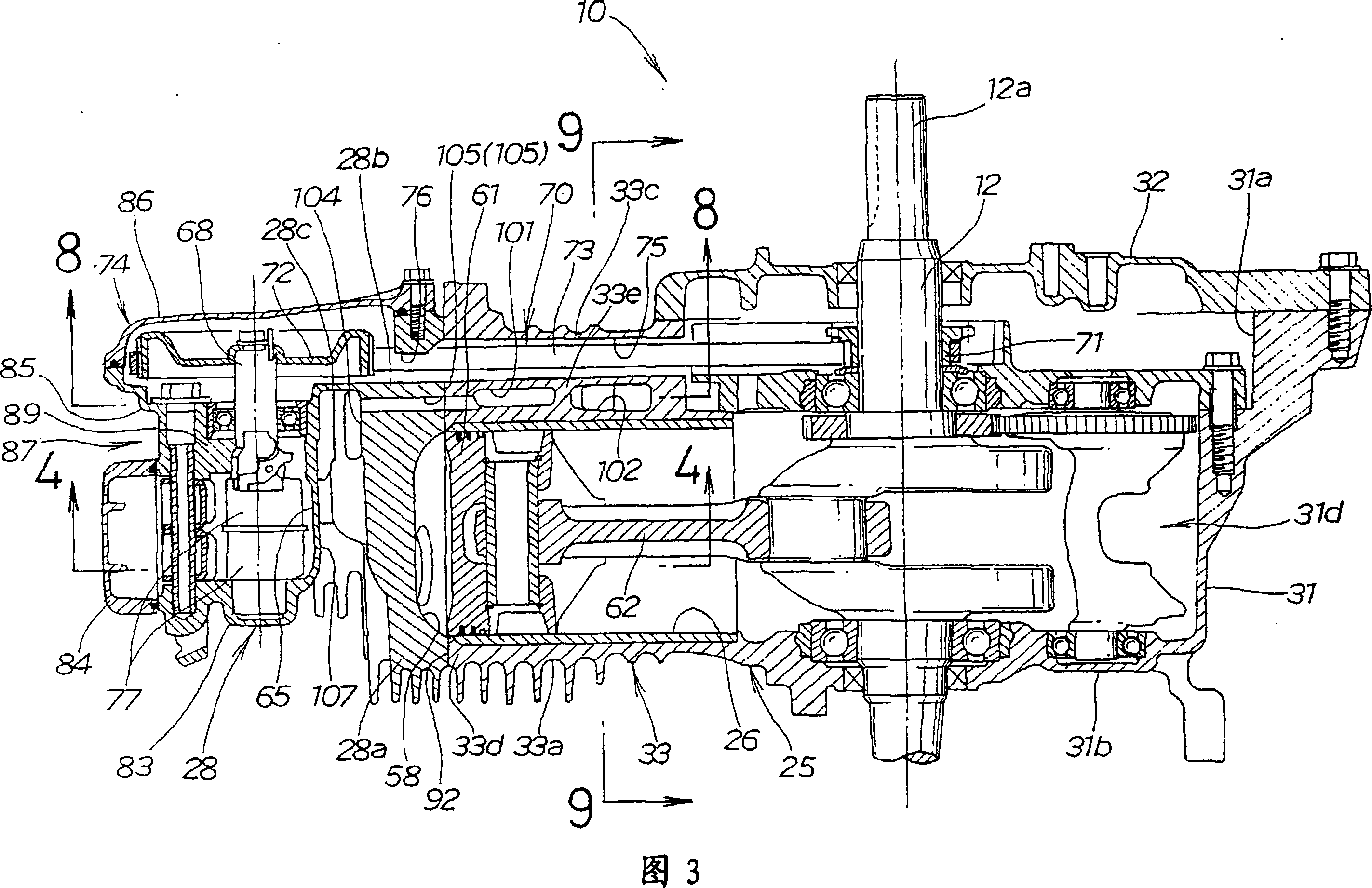
[0045] Both the cooling fan 13 and the recoil starter 18 are connected to the crankshaft 12 (see FIG. 3 ). The fan cover 15 has an opening 16 through which a recoil starter 18 can pass.

[0046] As shown in FIGS. 2 and 3 , the air-cooled engine 10 is a so-called OHC (Overhead Camshaft) single-cylinder engine with inclined cylinders, wherein the single cylinder 26 and the cylinder block 33 are located at the bottom of the crankcase 31 relative to the The horizontal base 34 is inclined upward at a fixed angle. The air-cooled engine 10 will be described in detail below.

[0047] The housing 25 of the air-cooled engine 10 includes a crankcase 31, a case cover 32 for closing the opening 31a of the crankcase 31, a cylinder block...


PUM


Abstract

An air-cooled engine (10) cooled by cooling air (Wi). The air-cooled engine (10) includes a cylinder block (33) and a cylinder head (28). The cylinder block (33) has cylinder cooling passages (101, 102) capable of transmitting cooling air (Wi) on the outer periphery of the cylinders (26). The cylinder head (28) has cylinder head cooling ducts (104) capable of conveying cooling air (Wi). The cylinder cooling passage (101, 102) and the cylinder head cooling passage (104) extend in a direction perpendicular to the axis (109) of the cylinder (26), and communicate with each other through connecting passages (105, 105).

Description

technical field [0001] The invention relates to an air-cooled engine cooled by cooling air. Background technique [0002] Air-cooled engines are forcibly cooled by cooling air sent to the cylinder head and cylinder block by a cooling fan driven by the crankshaft. This type of air-cooled engine is disclosed in Japanese Laid-Open Patent Application No. 2-275021 and Japanese Examined Utility Model Application No. 58-19293. [0003] In the air-cooled engine disclosed in Japanese Laid-Open Patent Application No. 2-275021, opening and closing of intake and exhaust valves is a result of rotation of a camshaft by a crankshaft via a power transmission mechanism. In this air-cooled engine, the combustion chamber in the cylinder head and the cylinders in the cylinder block are cooled by cooling air sent from the cooling fan to the cylinder head and cylinder block. In order to increase the cooling efficiency of the cooling air, it is preferable to direct the cooling air to the area ne...

Claims


Application Information

Patent Timeline
IPC IPC(8): F01P1/02F02F1/06B22D15/02
Inventor 佐藤义一筱田明久小川和久
Owner HONDA MOTOR CO LTD
Why Eureka
Try Eureka