Zero point correction device of angular velocity sensor
An angular velocity sensor and acceleration sensor technology, which is used in measurement devices, velocity/acceleration/shock measurement, instruments, etc., can solve the problems of large and expensive angular velocity sensors, and achieve the effect of avoiding the accumulation of integration errors and having a simple structure.
- Summary
- Abstract
- Description
- Claims
- Application Information
AI Technical Summary
Problems solved by technology
Method used
Image

Examples
no. 1 example
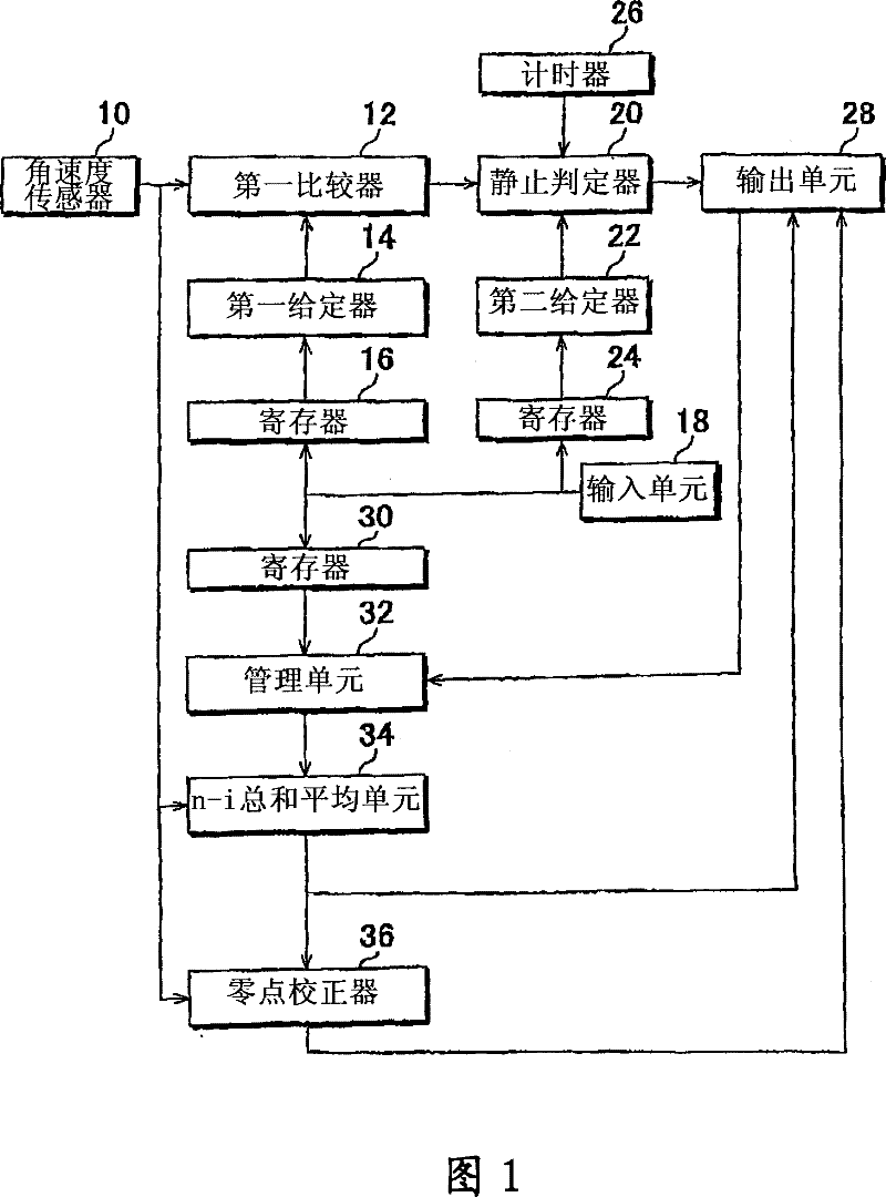
[0022] figure 1 A structural block diagram of this embodiment is shown. The angular velocity sensor 10 is provided at a predetermined position in a moving body such as a robot, and detects the angular velocity of the moving body. For example, the angular velocity sensor 10 employs an xyz orthogonal coordinate system as a sensor coordinate system, and detects angular velocities about axes, ie, the x-axis, y-axis, and z-axis. The angular velocity sensor 10 outputs the detected angular velocity to the first comparator 12 .
[0023] The first comparator 12 compares the variation width (fluctuation width) of the input angular velocity with a predetermined range in magnitude. The predetermined range is set by the first setter 14 . The first setter 14 may set a fixed range as the predetermined range. like figure 1 As shown, it is also possible to provide a structure in which the range set by the register 16 is set as a predetermined range, and the user can set a desired range in...
no. 2 example
[0038] Figure 7 A structural block diagram of this embodiment is shown. exist figure 1 In the embodiment of the present invention, the angular velocity from the angular velocity sensor 10 is used for determination related to the stationary state of the robot. However, in the second embodiment, the acceleration from the acceleration sensor provided in the same robot is used for determination related to the stationary state.
[0039] The acceleration sensor 40 detects accelerations in robot axial directions, ie, x-axis, y-axis, and z-axis directions, and outputs the accelerations to the second comparator 42 .
[0040] The second comparator 42 compares the predetermined range set in the third setter 44 with the variation width of the acceleration in magnitude, and outputs the comparison result to the third comparator 48 . The predetermined range is set by the third setter 44 . The third giver 44 may set a fixed range as the predetermined range. like Figure 7 As shown, it ...
no. 3 example
[0043] Figure 8A and 8B A structural block diagram of this embodiment is shown. In the described embodiment, both angular velocity and acceleration are used as standstill related determinations.
[0044] Using angular velocity to determine structures at rest and figure 1 The structures shown are similar. However, the first comparator 12 outputs the comparison result to the combination comparator 50 instead of the static determiner 20 .
[0045] On the other hand, structures that use acceleration to determine a stationary state are the same as Figure 7 The structures shown are similar. However, the third comparator 48 outputs the comparison result to the combined comparator 50 instead of the static determiner 20 .
[0046] The combined comparator 50 inputs the comparison result from the first comparator 12 and the comparison result from the third comparator 48, if the two comparison results are within a certain range, then it is determined that the robot is in a station...
PUM
 Abstract
Description
Claims
Application Information
 - R&D
- Intellectual Property
- Life Sciences
- Materials
- Tech Scout
- Unparalleled Data Quality
- Higher Quality Content
- 60% Fewer Hallucinations
Browse by: Latest US Patents, China's latest patents, Technical Efficacy Thesaurus, Application Domain, Technology Topic, Popular Technical Reports.
© 2025 PatSnap. All rights reserved.Legal|Privacy policy|Modern Slavery Act Transparency Statement|Sitemap|About US| Contact US: help@patsnap.com