Electric stove

A technology of electric furnace and power supply, which is applied in the direction of household furnace/stove, electric heating fuel, heating arrangement of electric heating plate, etc. It can solve the problems of difficulty in realizing automation and lack of automation, so as to realize automatic control, ensure normal operation and reduce the temperature in the furnace Effect

Inactive Publication Date: 2008-08-06
方文新
View PDF0 Cites 2 Cited by
  • Summary
  • Abstract
  • Description
  • Claims
  • Application Information

AI Technical Summary

Problems solved by technology

[0002] Traditional electric furnaces use electric heating plates as heating elements, and traditional electric furnaces with high power above 1000W are difficult to automate
The main reason is that the temperature in the furnace is too high. After the electric heating plate is connected to the power supply, it continuously emits heat. The heat emitted by the electric heating plate is not only transmitted to the heated container on the electric heating plate, but also transfers heat to the inside of the furnace body through the air. The normal working temperature of the furnace surface is 500°C-600°C (when using a ceramic pot or glass pot), the temperature in the furnace is as high as 400°C-500°C, the operating temperature of civil electronic devices is 85°C, and the thermal deformation temperature of ordinary plastic is about 100°C. The difference is too far. Any automatic device, Any plastic can't bear it. The current high-power traditional electric furnaces all use iron shells as the furnace base, which are manually operated and used without automation.

Method used


Image

  • Electric stove
  • Electric stove
  • Electric stove

Examples


Embodiment Construction

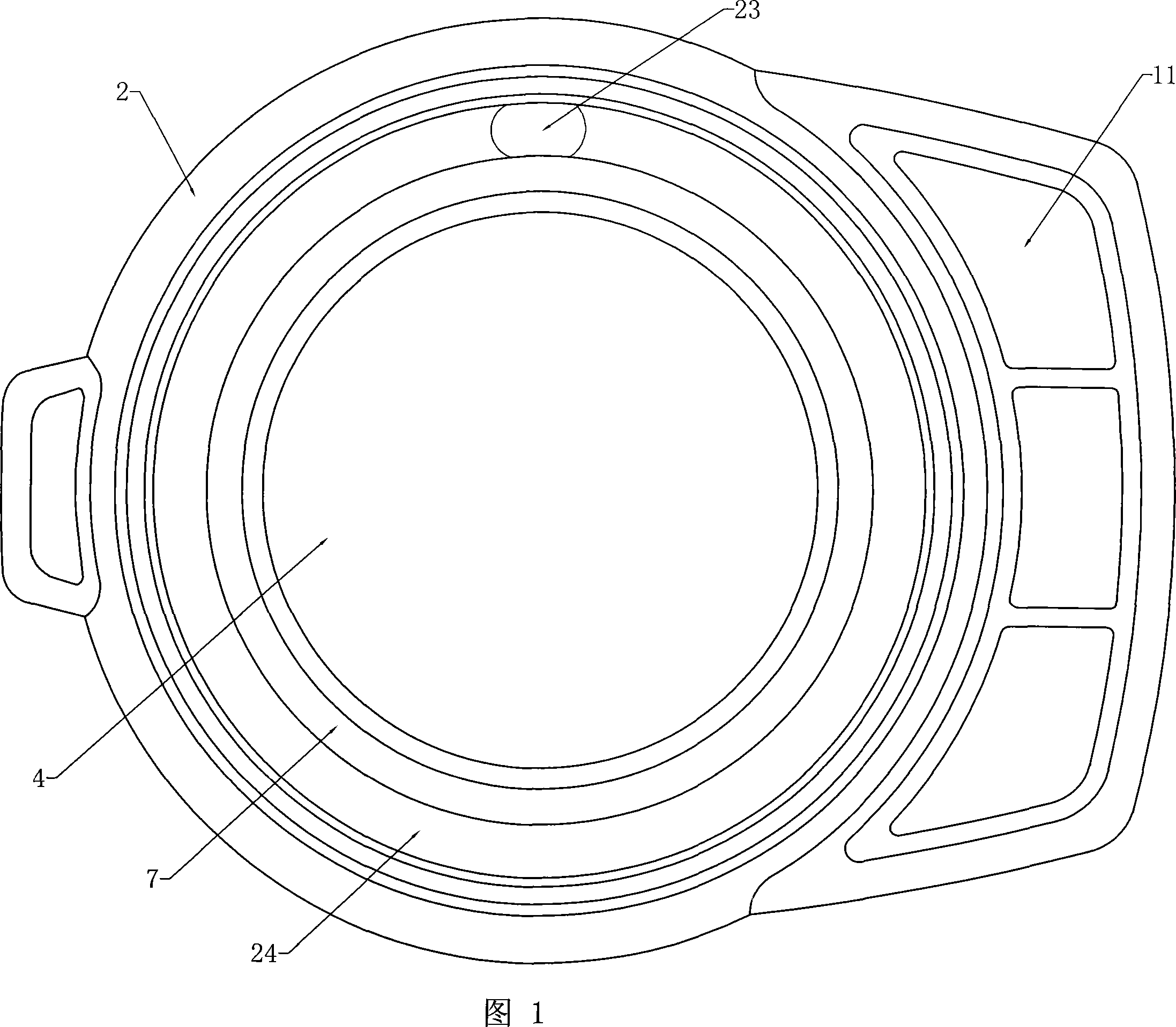
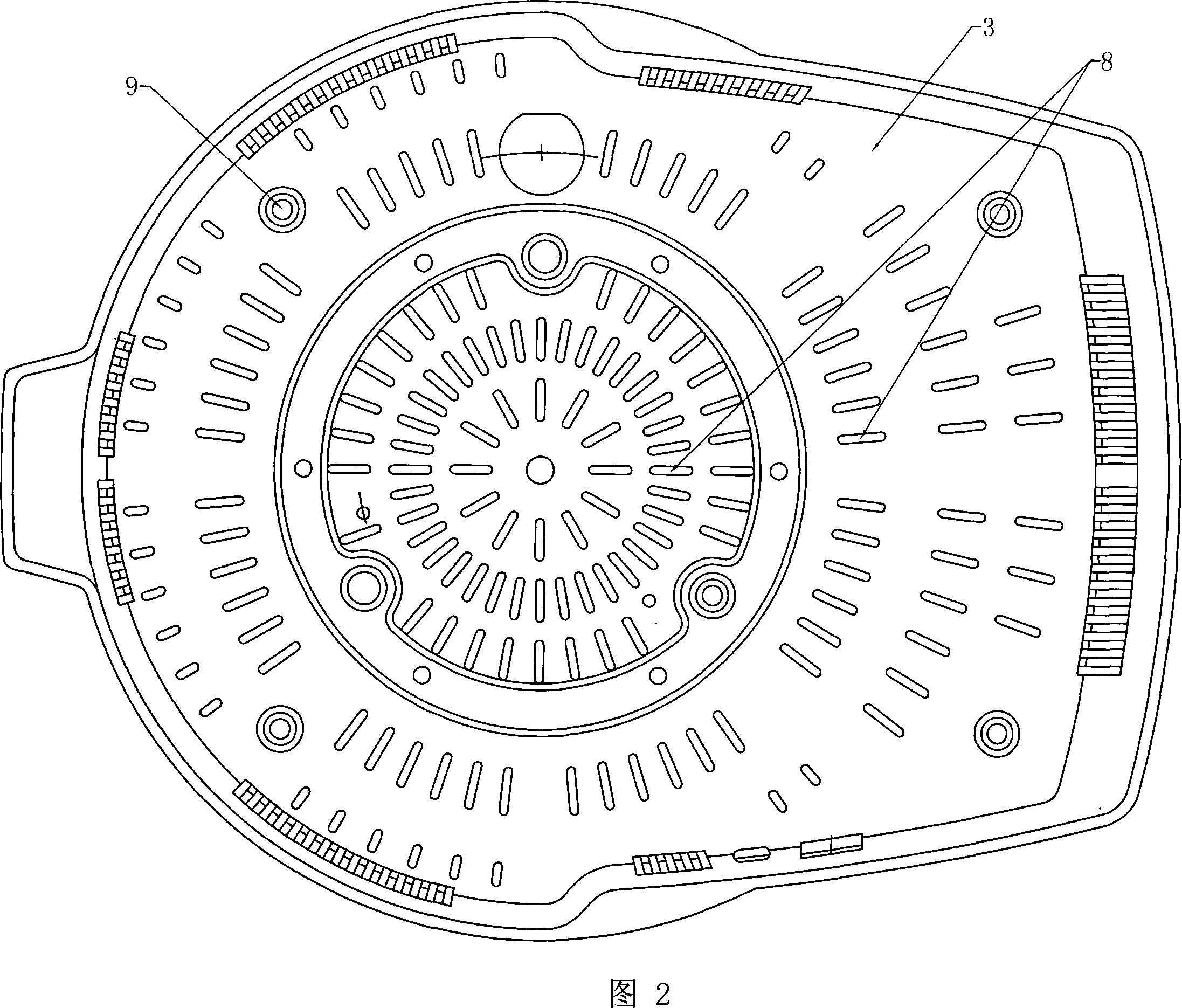
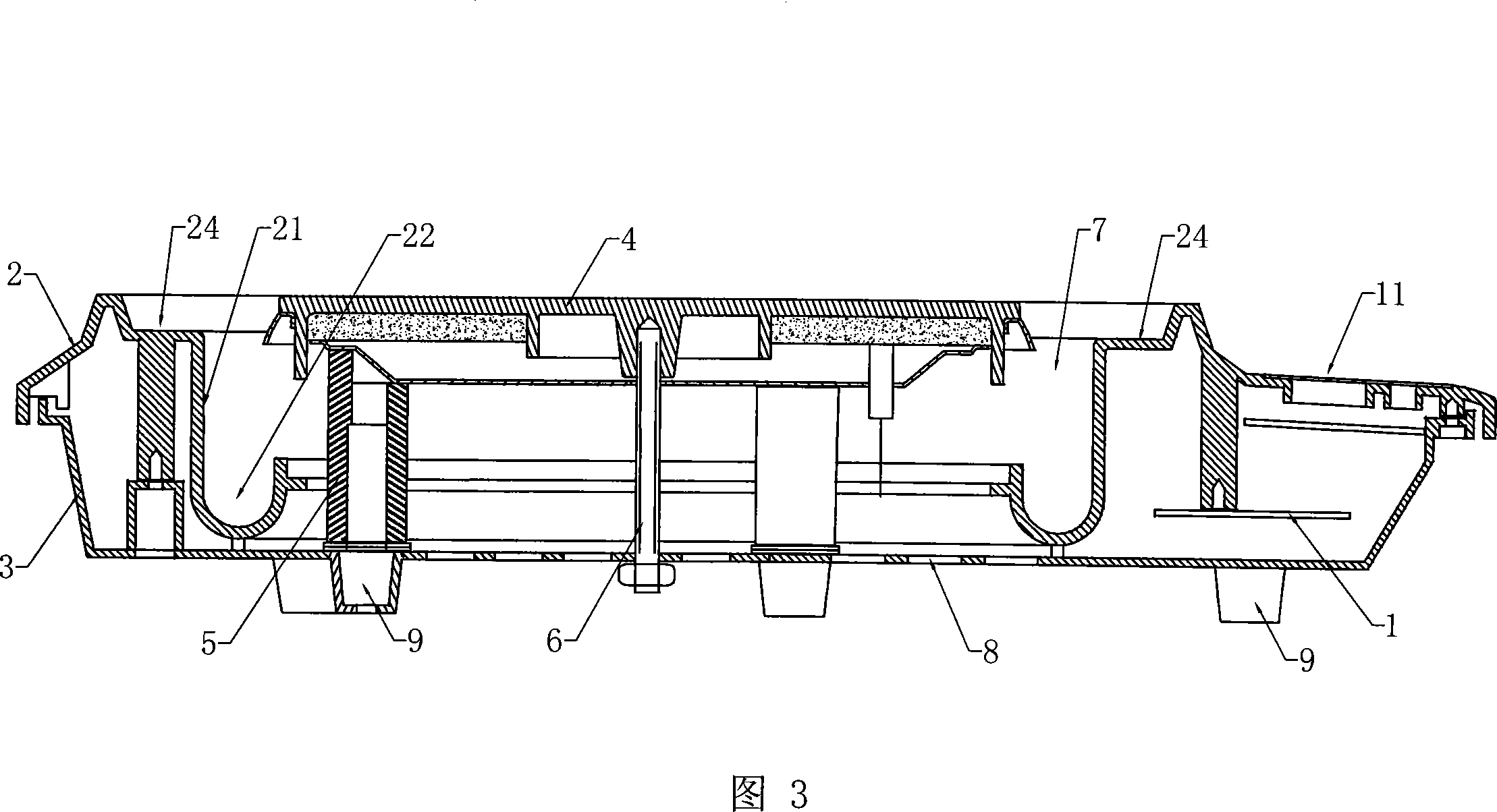
[0012] Referring to Fig. 1-Fig. 4, the electric furnace includes an upper shell 2, a lower shell 3, an electric heating plate 4 and a control circuit board 1, the control circuit board 1 is arranged under the front part of the upper shell 2, and the control circuit board 1 is respectively It is connected with the power supply, the control panel 11 and the electric heating plate 4. On the upper shell 2, there is a cavity for accommodating the electric heating plate 4 and a soup overflow tank 24. The electric heating plate 4 is supported by three porcelain columns 5 and tightened by screws and nuts 6. Fixed on the lower casing 3, between the electric heating plate 4 and the cavity wall 21 of the upper casing 2, an isolation groove 7 is provided, and the isolation groove 7 communicates with the vent hole 8 on the lower casing 3. In the isolation groove 7 The bottom of the soup row is provided with a soup row tank 22, and the tank body of the soup row tank 22 is connected with the ...


PUM


Abstract

The invention relates to an electric furnace which employs an electric hot tray as a heating element, and the electric furnace comprises a casing stand, the electric hot tray and a control circuit board. The control circuit board is respectively connected with power supply, a control panel and the electric hot tray, and the casing stand is formed by an upper casing and a lower casing. A cavity for containing the electric hot tray is arranged on the upper casing, the electric hot tray is supported by knob insulators and firmly fixed on the lower casing through screws and nuts, an isolation groove is arranged between the electric hot tray and the wall portion of the cavity of the upper casing, and the isolation groove is communicated with vent holes arranged on the lower casing. When the power of the electric hot tray is on for heating, temperature inside the furnace is relatively high, and hot air naturally ascends while cold air supplements from the vent holes at the bottom of the furnace to form convective flowing, thereby largely reducing the temperature inside the furnace, guaranteeing the normal operation of an electronic control circuit and realizing automation of high power conventional electric furnaces.

Description

Technical field: [0001] The invention relates to an electric furnace, in particular to an electric furnace using an electric heating plate as a heating element. Background technique: [0002] Traditional electric furnaces use electric heating plates as heating elements, and traditional electric furnaces with high power above 1000W are difficult to automate. The main reason is that the temperature in the furnace is too high. After the electric heating plate is connected to the power supply, it continuously emits heat. The heat emitted by the electric heating plate is not only transmitted to the heated container on the electric heating plate, but also transfers heat to the inside of the furnace body through the air. The normal working temperature of the furnace surface is 500°C-600°C (when using a ceramic pot or glass pot), the temperature in the furnace is as high as 400°C-500°C, the operating temperature of civil electronic devices is 85°C, and the thermal deformation temper...

Claims


Application Information

Patent Timeline
Patent Type & Authority Applications(China)
IPC IPC(8): F24C7/00F24C7/06F24C15/14
CPCH05B3/70
Inventor 方文新
Owner 方文新
Why Eureka
Try Eureka