
Vertical pressure charging press-shoot system

A technology of booster cylinder and booster oil cylinder, which is applied in the field of die casting machines, can solve the problems of short booster pressure build-up time, short booster stroke, breakage and shedding, etc. The effect of short injection and booster flow channels and short pressure build-up time

Active Publication Date: 2008-08-13
SUZHOU SANJI FOUNDRY EQUIP
View PDF0 Cites 17 Cited by
  • Summary
  • Abstract
  • Description
  • Claims
  • Application Information

AI Technical Summary

Problems solved by technology

[0007] 1. The second-speed pressure oil must enter the back cavity of the injection cylinder through the gap between the floating piston and the booster piston rod. Due to the limitation of the diameter of the injection cylinder, the strength of the three parts of the floating piston, booster piston rod and hole plate, There is a bottleneck in the oil passing area of ​​the second-speed pressure oil, and this mechanism is not conducive to the instant speed increase of fast injection
[0008] 2. In order to increase the oil passing area of ​​the second speed, it is necessary to increase the gap between the booster piston rod and the floating piston. The prerequisite for the booster of this mechanism is that the booster piston and the floating piston are reliably closed. The larger the gap, the floating piston is closed. The longer the time is, it will inevitably prolong the pressure build-up time
Therefore, this mechanism is not conducive to simultaneously taking into account the faster speed of the second speed and the shorter boost pressure build-up time
[0009] 3. The hole plate has been subjected to high-pressure oil and high-speed floating piston impact for a long time, and it is very easy to break and fall off, posing a safety hazard
[0010] 4. It is difficult to observe the operation status of the booster stroke
[0011] 5. The booster stroke is short, and the booster piston is placed in the oil circuit control panel, which makes it inconvenient to start the booster cylinder in advance during the filling stage to achieve high-energy filling

Method used


Image

  • Vertical pressure charging press-shoot system
  • Vertical pressure charging press-shoot system
  • Vertical pressure charging press-shoot system

Examples


Embodiment Construction

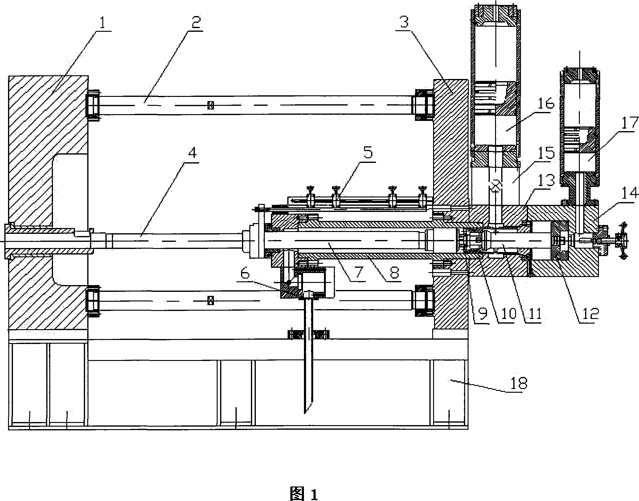
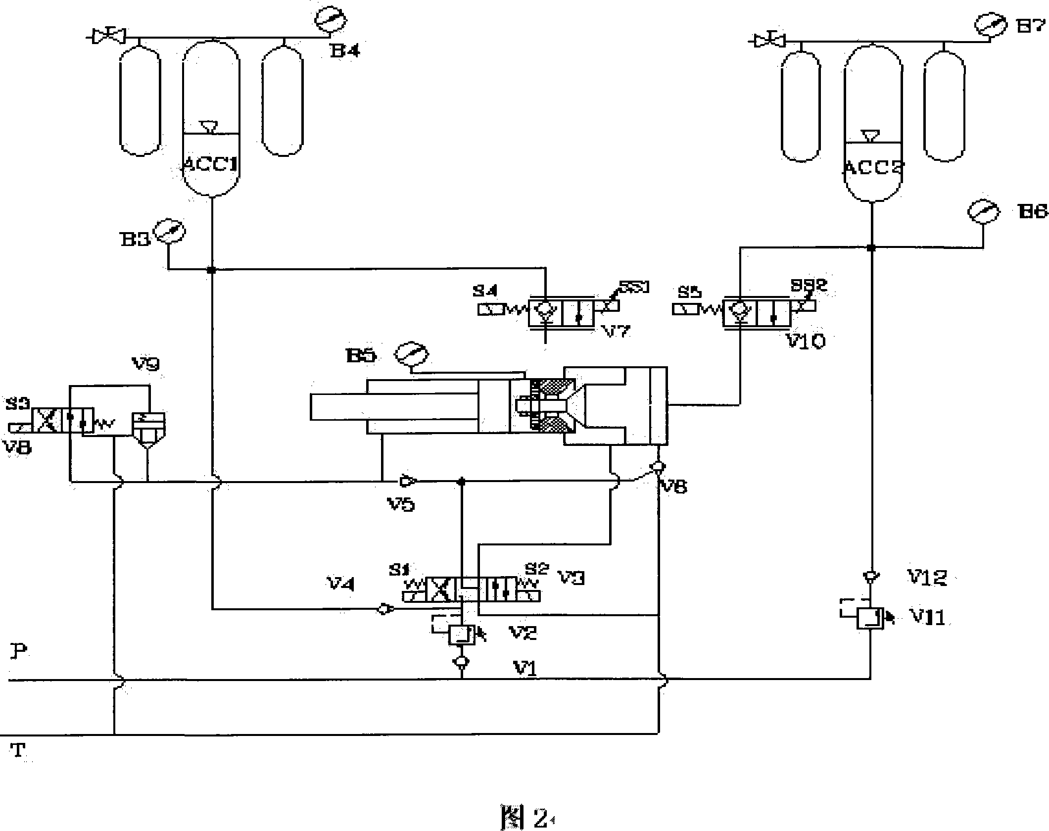
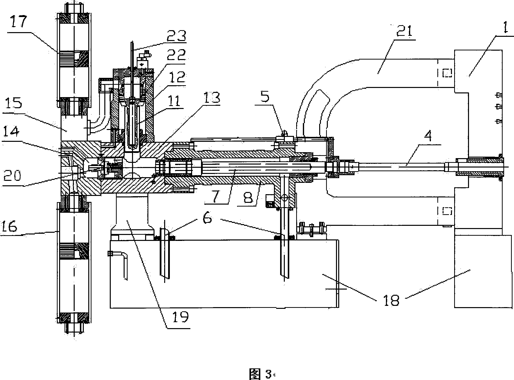
[0034]The present invention discloses a vertical pressurized injection system, which, like the prior art, includes a floor-standing machine base 18 and a fixed mold seat plate 1 fixed thereon as a mold clamping mechanism part of a die-casting machine. An injection cylinder is horizontally arranged on the machine base 18 opposite to the fixed mold seat plate 1 , and the injection cylinder includes an injection piston rod 7 and an injection cylinder barrel 8 . An injection punch assembly 4 is fitted between the injection piston rod 7 of the injection cylinder and the fixed mold seat plate 1 , and the injection cylinder and the fixed mold seat plate 1 are connected by a C-shaped frame 21 . A quick discharge assembly 6 , an oil passage middle plate 13 , and an oil passage tail plate 14 are matched with the injection cylinder. The injection oil circuit plate 19 is arranged on the oil circuit middle plate 13; the two-speed accumulator assembly 16 is arranged on the oil circuit tail ...


PUM


Abstract

The invention provides a vertical pressure charging pressing system capable of enhancing pressing property, stability and safety of a die casting machine by using a structure with a pressure charging oil cylinder perpendicular to an injection oil cylinder. The slow-press hydraulic oil and the quick-press hydraulic oil enter the rear cavity of an injection oil cylinder through a large-through-diameter solo valve. The pressure charging oil cylinder is perpendicular to the injection oil cylinder, disposed at the upper or lower part and between the solo valve and the injection plug. Two pressure charting starting modes are provided, one depends on pressure feedback of the injection oil cylinder rear cavity, and the other depends on displacement feedback of the injection oil cylinder. When the PLC or the process control machine receives the feedback signal, the pressure charging valve opens, the pressure charging oil cylinder starts to work, the pressure in the rear cavity of the injection oil cylinder increases quickly, the solo valve closes at the same time, and the pressure charging function is completed. The invented system is provided with following advantages: quick injection, the pressure charging channel is large and shot, quick injection speed, short pressure build-up time, long pressure charging distance, and high energy charging type.

Description

technical field [0001] The invention relates to a brand-new injection system of a die-casting machine, which is especially suitable for a die-casting machine with a clamping force greater than 1000TON (10000KN). Background technique [0002] Modern die-casting is a forming method of mold casting molten metal that can produce precise, beautiful and stable casting products under high-speed and high-pressure environments. Compared with plastic working such as forging, extrusion or machining, and low-pressure casting, die casting has the significant advantage of forming complex-shaped finished parts in a shorter time-consuming process. Therefore, the die-casting machine is suitable for producing various components with complex shapes at a low price, especially parts and components that require certain mechanical strength. Such as various hardware products, toys, motorcycle parts, auto parts, car engines, etc. [0003] Injection is the core technology of die casting machine, fa...

Claims


Application Information

Patent Timeline
Patent Type & Authority Applications(China)
IPC IPC(8): B22D17/12
Inventor 万水平袁耀原许善新
Owner SUZHOU SANJI FOUNDRY EQUIP
Learn More