Supercharge Your Innovation With Domain-Expert AI Agents!

Gasifier liner

A gasifier and bushing technology, applied in the details of the gasification device, the mechanical details of the gasification device, and the manufacture of combustible gas, can solve the problems of changing the performance and efficiency of the gasifier and weakening the ability of the combined power supply

Inactive Publication Date: 2008-08-13
ROCKETDYNE
View PDF1 Cites 1 Cited by
  • Summary
  • Abstract
  • Description
  • Claims
  • Application Information

AI Technical Summary

Problems solved by technology

[0005] Another challenge faced by regenerative cooling liners is establishing the specific implementation of the metal / ceramic joint required for the closed loop (regenerative) cooling circuit
In addition, there is a risk that small cracks in the liner could alter the performance and efficiency of the gasifier, thus impairing the cogeneration capability

Method used


Image

  • Gasifier liner
  • Gasifier liner
  • Gasifier liner

Examples


Embodiment Construction

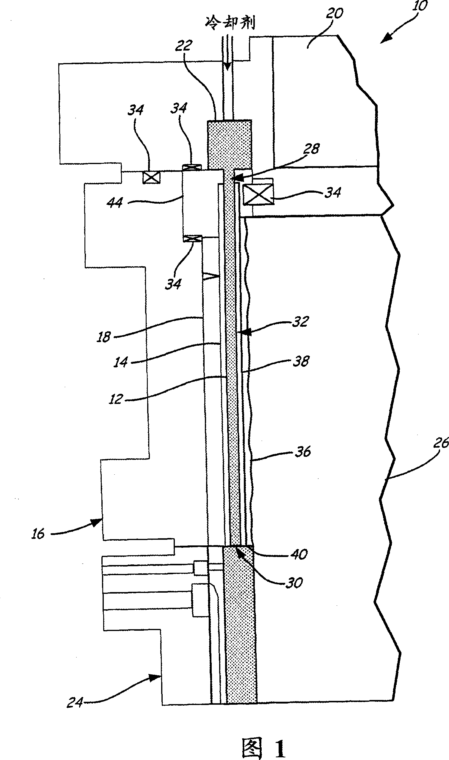
[0014] Figure 1 shows a cross-sectional view of a gasifier reactor 10 generally comprising a coolant passage 12, a representative liner 14, a metallic pressure vessel 16, an insulator 18, an injector 20, a coolant inlet Manifold 22 , quench section 24 and reaction chamber 26 . The use of the liner 14 in the gasifier reactor 10 provides low cost and extended life of the gasifier reactor 10 compared to other liners. Various technical risks of the gasification process are also reduced by the liner 14, as metal / ceramic bonding problems, crack propagation leading to leaks, and thermal growth mismatch are reduced or eliminated. The configuration of the liner 14 in the gasifier reactor 10 also allows for increased structural integrity of the coolant passage 12 . The liner 14 can be used in both a bleed air cooled liner cooling scheme and a regeneratively cooled liner cooling scheme in which coolant is poured into the gasification tank at the back end of the gasifier In the regenera...


PUM


Abstract

A gasifier liner is used in a gasifier vessel and includes a plurality of elongated channels and a plurality of ceramic sheaths. The elongated passage carries coolant through the gasifier. The ceramic sheath surrounds the elongated channel.

Description

technical field [0001] The present invention relates to a gasifier liner for use in a gasifier vessel. Background technique [0002] The gasification process involves turning coal or other carbonaceous materials into synthesis gas. Since the cost of coal is lower than that of natural gas and oil, there is a strong economic incentive to develop gasification technology. The problem with existing gasification technologies is that these technologies typically have high capital costs and / or relatively low availability. Utilization refers to the amount of time equipment is online and manufacturing products. One cause of low utilization is complex or short-lived gasifier liner designs. Examples of liners currently used in gasifiers are refractory liners, film liners, and regenerative cooling liners. The refractory lining requires annual replacement of the refractory material, and the utilization rate is about 90%. Although membrane liners have a longer life than refractory lin...

Claims


Application Information

Patent Timeline
Patent Type & Authority Applications(China)
IPC IPC(8): C10J3/74
CPCC10J3/485C10J3/74C10J2200/09C10J2200/152F27D1/045F27D1/12
Inventor M·A·费茨西蒙斯S·A·尤斯S·P·富塞尔曼
Owner ROCKETDYNE
Features
  • R&D
  • Intellectual Property
  • Life Sciences
  • Materials
  • Tech Scout
  • Unparalleled Data Quality
  • Higher Quality Content
  • 60% Fewer Hallucinations
Learn More