Combined hood-type furnace annealing method and annealing furnace device thereof

A bell furnace and combined technology, which is applied in the annealing field of the combined bell furnace, can solve the problems that the heat cannot be recycled, the labor intensity is high, the equipment and production costs are reduced, and the equipment investment and operating costs can be saved, and the heating can be improved. and cooling efficiency, the effect of shortening the annealing cycle

Active Publication Date: 2008-08-13
SHIJIAZHUANG XINHUA IND FURNACE CO LTD
View PDF0 Cites 19 Cited by
  • Summary
  • Abstract
  • Description
  • Claims
  • Application Information

AI Technical Summary

Problems solved by technology

The disadvantages of the existing steel bell furnace annealing are: the bell furnace is heated or cooled separately during the annealing process, and the heat cannot be recycled, resulting in a waste of energy; the use of the heating hood to indirectly heat the steel in the protective hood resul...

Method used


Image

  • Combined hood-type furnace annealing method and annealing furnace device thereof
  • Combined hood-type furnace annealing method and annealing furnace device thereof
  • Combined hood-type furnace annealing method and annealing furnace device thereof

Examples


Embodiment 1

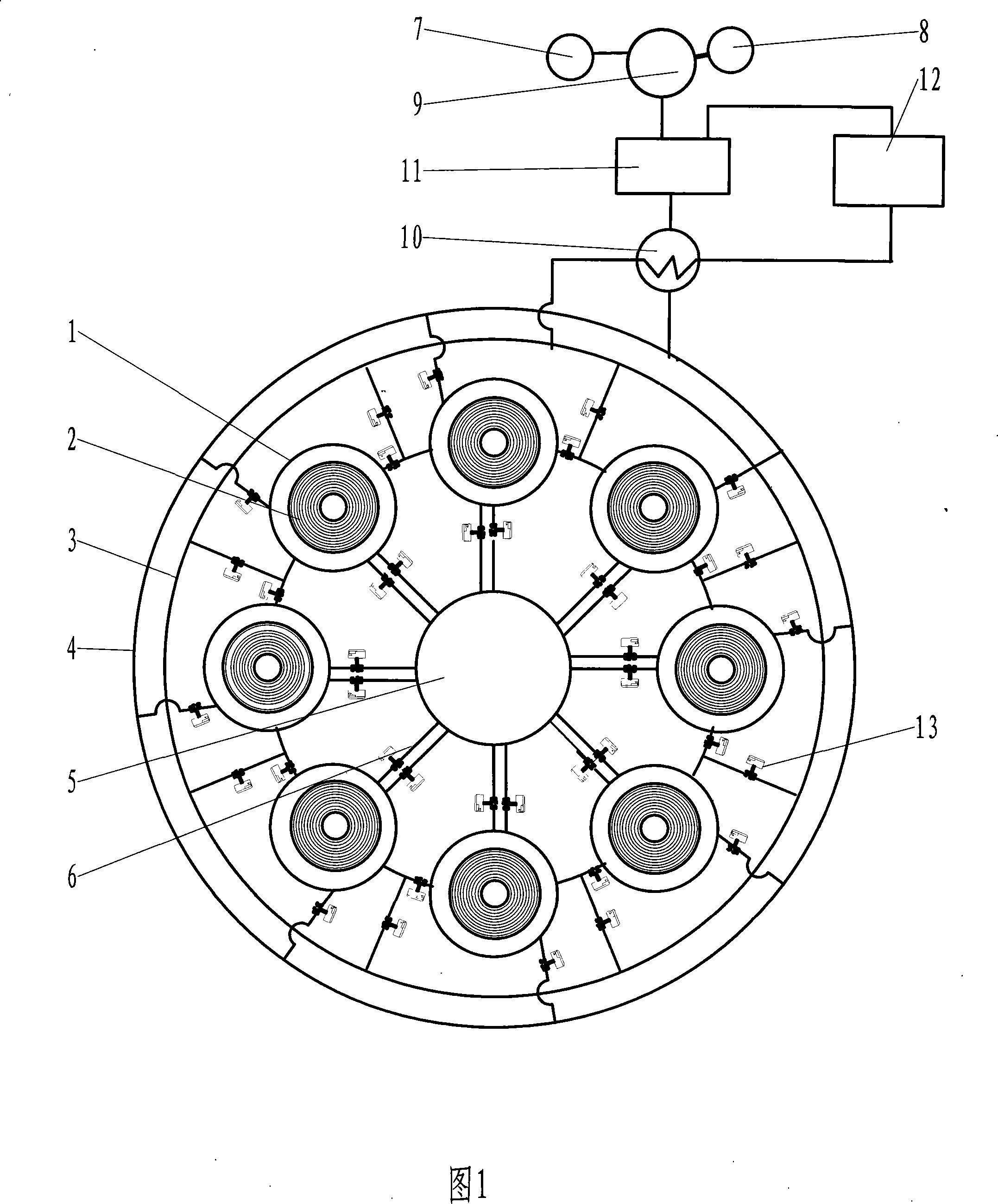
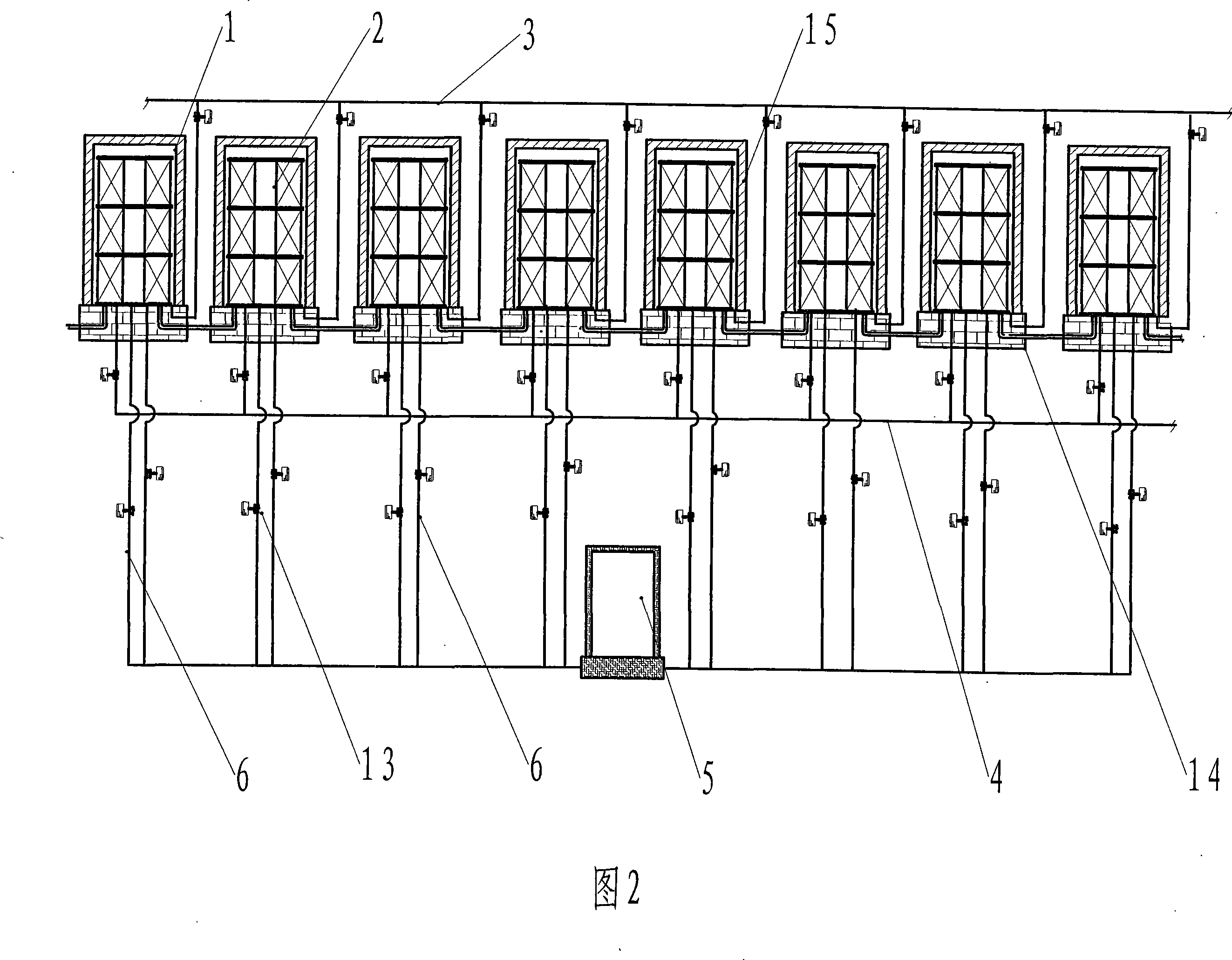
[0019] The present invention, as shown in Figure 1 and Figure 2, is an annealing furnace device composed of 8 bell furnaces, and the annealed material is cold-rolled strip steel. The annealing furnace device includes bell furnace 1, hydrogen production equipment 8, nitrogen generator 7, protective gas supplement tank 9, protective gas filter 11, heat exchanger 10, circulating fan 12, cooling and cleaning protective gas pipe network 4, turbid gas The discharge pipe 3 has a furnace platform 14 and a protective cover 15 in the bell furnace 1 . Figure 1 shows a circular arrangement structure, 8 bell furnaces are installed in series, and are connected from the outlet of the previous bell furnace to the entrance of the next bell furnace in turn. Each bell-type furnace communicates with the cool and clean protective gas pipe network 4 and the turbid gas discharge pipe 3 respectively. The shielding gas heater 5 is located in the center of the device, and the heater is electric heatin...

Embodiment 2

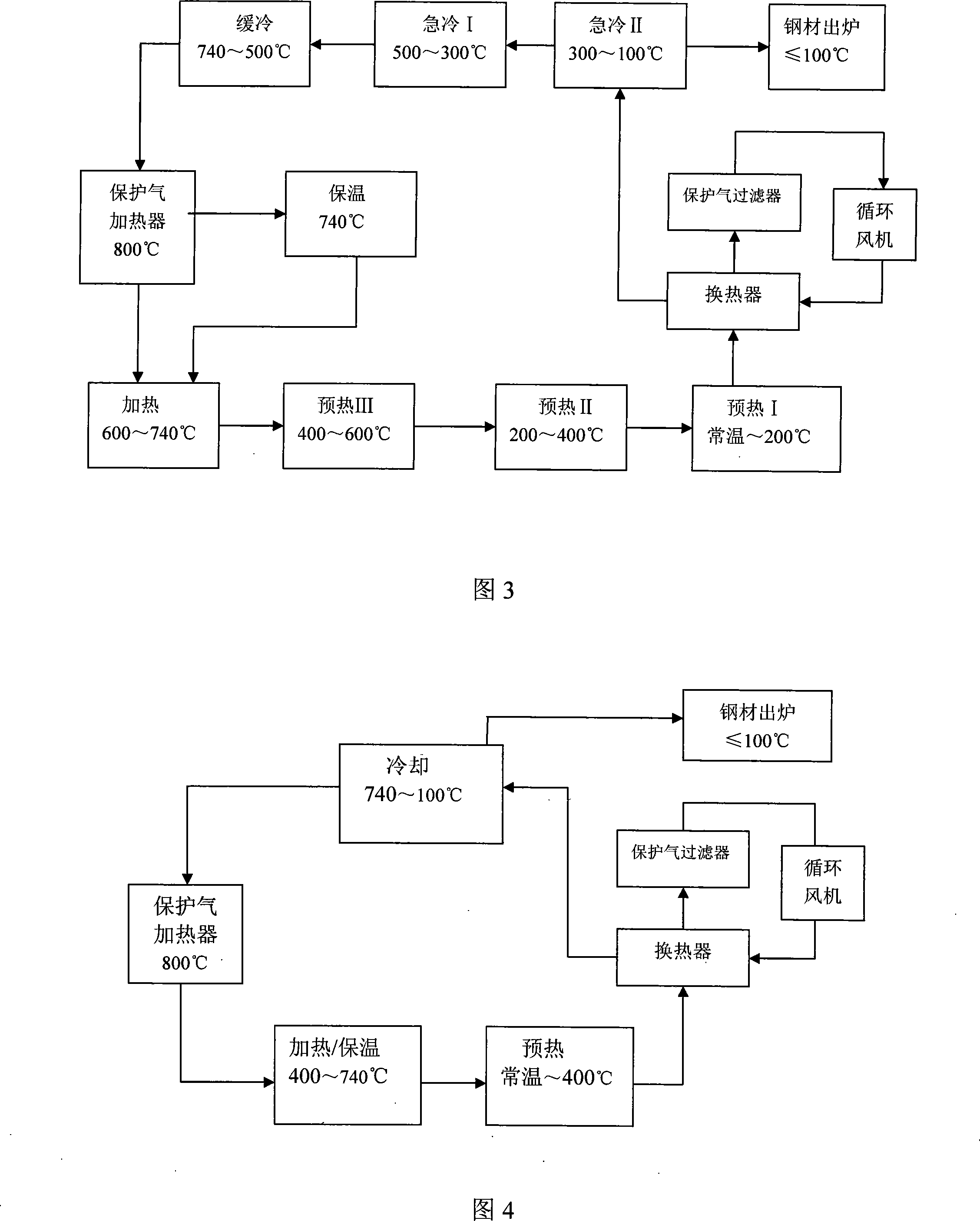
[0025] The annealing process and temperature of another solution of the present invention are shown in Figure 4, which is an annealing furnace device composed of three bell furnaces, and the material to be annealed is a steel product. The hot net shielding gas heated in the shielding gas heater first enters the bell-type furnace in the heating / insulation stage, and enters the bell-type furnace in the preheating stage from the heating / insulation stage, and the shielding gas coming out of the preheating stage After heat exchange, filtration and purification, it enters the cooling stage through the circulating fan, and the protective gas that takes out heat from the cooling stage returns to the protective gas heater; the annealing of steel products is carried out according to the process of preheating, heating / insulation, and cooling, and the annealed steel products are cooled to Baked out below 100°C. The composition of the protective gas used is: nitrogen: 70%; hydrogen: 30%. ...


PUM


Abstract

The invention relates to a combined cover annealing method and annealing furnace device thereof. At least two cover furnaces are installed in series, protecting gas central heater and matched feeding device are provided, using the heated protecting gas, preheat, heat, heat-insulate and cool the annealing material inside of the protective cover, the protecting gas circularly flows in the cover furnace during the annealing process, the excessive heat at high temperature stage is transferred to the next low temperature stage, the low temperature protecting gas returns to the protecting gas heater after the cooling stage, the turbid gas returns to the protecting gas system for used after filtering. Compared with current technology, the advantages of the invention reside in: the heat during the annealing process is recycling, which saves 30% to 40% of energy; no heating cover or cooling cover is used during the annealing process, heat or cool material inside the protective cover by protecting gas, which simplifies the operation process, saves equipment cost and operation expense, and the annealed material has good quality.

Description

technical field [0001] The invention relates to a combined bell furnace annealing method and an annealing furnace device, belonging to the field of material heat treatment. Background technique [0002] Material annealing mainly has two basic functions, one is to eliminate the hardening and residual stress generated during processing, soften the material, improve plasticity, and facilitate further processing; the other is to change the structure of the material to obtain the required grain size and grain size. Orientation. Bell furnace annealing is one of the main technologies for heat treatment of cold-rolled steel. It is to stack several coils of steel into stacks, cover them with a protective cover, heat them up, reach the specified annealing temperature, and then cool after heat preservation. Generally, the annealing of the bell furnace adopts the single-stack or multi-stack type. After the steel is stacked, the protective cover is put on, the protective gas is introduc...

Claims


Application Information

Patent Timeline
IPC IPC(8): C21D1/00
Inventor 贾会平余游
Owner SHIJIAZHUANG XINHUA IND FURNACE CO LTD
Why Eureka
Try Eureka