Generator of circularly polarized wave

A technology of circularly polarized waves and generators, which is applied in waveguide devices, waveguide openings, electrical components, etc., and can solve the problems of circularly polarized wave generators, such as the performance degradation of resistance to power consumption and low loss, difficulty in mass production and price reduction, etc. Problems, to achieve the effect of low power consumption resistance, easy processing, and reduced characteristic deterioration

Inactive Publication Date: 2008-08-13
MITSUBISHI ELECTRIC CORP
View PDF1 Cites 0 Cited by
  • Summary
  • Abstract
  • Description
  • Claims
  • Application Information

AI Technical Summary

Problems solved by technology

[0010] Since the conventional circularly polarized wave generator is configured as above, it has a structure in which the metal pillar 2 protrudes into the circular waveguide 1, and as a result, an external disturbance is supplied to a portion in the circular waveguide 1 where the electric field distribution is dense. To delay the phase, a small change in the amount of insertion of the metal post 2 into the circular waveguide 1 will cause a large change in the amount of phase delay or reflection. Therefore, in order to obtain the desired passing phase characteristics or reflection It takes a lot of time to adjust the amplitude characteristics, making mass production difficult and price reduction difficult
[0011] In addition, since a plurality of metal objects, that is, metal pillars 2 protrude into the portion where the electric field distribution in the circular waveguide 1 is relatively dense, the performance of the circularly polarized wave generator with respect to power consumption and the performance of low loss deteriorates. The problem

Method used


Image

  • Generator of circularly polarized wave
  • Generator of circularly polarized wave
  • Generator of circularly polarized wave

Examples


Embodiment Construction

[0065] Hereinafter, in order to explain the present invention in more detail, the best mode for carrying out the invention will be described with reference to the drawings.

[0066] Embodiment 1

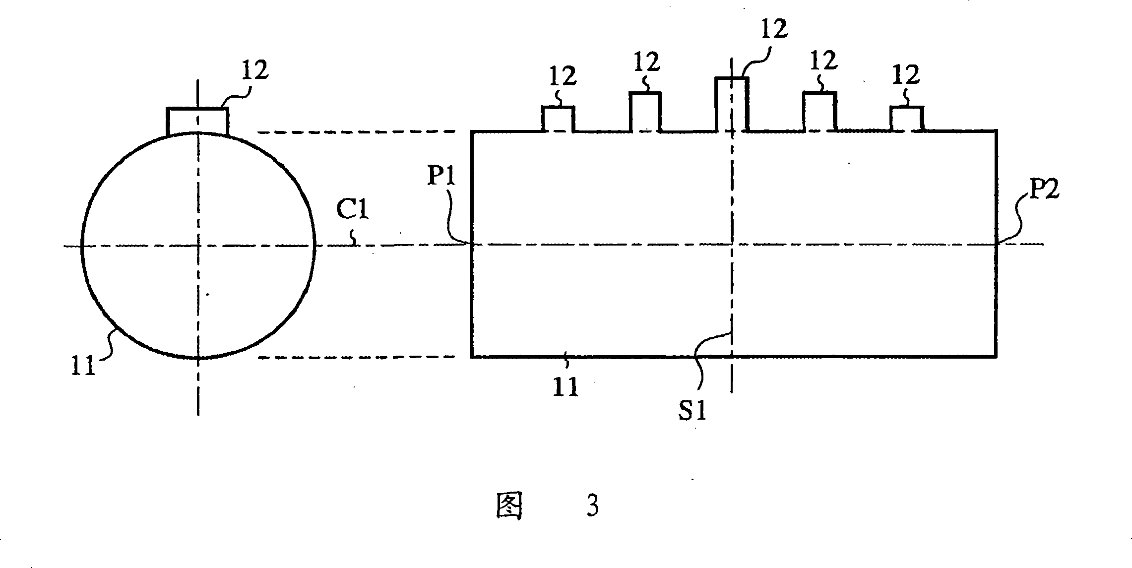
[0067] 3 is a schematic structural view showing a circularly polarized wave generator according to Embodiment 1 of the present invention. In the figure, 11 is a circular waveguide, and 12 is a plurality of side grooves, and the plurality of side grooves are opposite to the circular waveguide. 11 The plane S1, which is equally divided into left and right halves, is arranged on the side wall of the circular waveguide 11 along the direction of the tube axis C1 in such a manner that the volume is large at its central part, and between the input end P1 and the output end P2 The volume in the direction is small, and it becomes a symmetrical structure. 4 is an explanatory diagram showing electromagnetic field distribution of incident waves according to Embodiment 1 of the present invention...


PUM


Abstract

The present invention aims at providing a circular waveguide polarizer with high performance and low cost. The circular waveguide polarizer is realized by arranging a plurality of side grooves 12 in a side wall of a circular waveguide 11 along the direction of a pipe axis C1 and by appropriately designing the number, spacing, radial depth, circumferential width, length in the pipe axis direction, and the like. According to this circular waveguide polarizer, disturbance is imparted to a section with a coarse electromagnetic field distribution in a transmission mode to create a phase delay, so that the amount of phase delay does not vary largely with a delicate change in width, depth and length of the side grooves 12. That is, there is little deterioration in characteristics caused by a machining error or the like, and hence it becomes possible to effect mass production and cost reductions.

Description

[0001] This application is a divisional application of: [0002] Application number: 00803700.0 (PCT / JP00 / 08689) [0003] Filing date: December 8, 2000 (earliest priority date: December 10, 1999) [0004] Invention Name: Circularly Polarized Wave Generator technical field [0005] The present invention mainly relates to a circularly polarized wave generator used in VHF frequency band, UHF frequency band, microwave frequency band and millimeter wave frequency band. Background technique [0006] Fig. 1 is, for example, a schematic configuration diagram of a conventional circularly polarized wave generator shown in the Journal of the Society of Electronics and Communications (published in 1980, Vol.63-B, No.9, pp908-915). In the figure, 1 is a circular waveguide, 2 is a plurality of metal posts inserted from the side wall of the circular waveguide 1 in pairs relative to the tube axis C1 of the circular waveguide 1, and, relative to the circular waveguide 1 The direction of t...

Claims


Application Information

Patent Timeline
Patent Type & Authority Applications(China)
IPC IPC(8): H01P1/17H01Q13/06H01Q15/24
CPCH01Q13/06H01Q15/242H01P1/171
Inventor 米田尚史宫崎守
Owner MITSUBISHI ELECTRIC CORP
Why Eureka
Try Eureka