broadband filter antenna

A filter antenna, broadband technology, applied in the field of broadband filter antenna, can solve the problems of low efficiency, large size, narrow operating bandwidth, etc., to achieve filtering performance, improve out-of-band suppression, and improve the effect of frequency selectivity on both sides

Active Publication Date: 2020-09-15
南通大学技术转移中心有限公司
View PDF7 Cites 0 Cited by
  • Summary
  • Abstract
  • Description
  • Claims
  • Application Information

AI Technical Summary

Problems solved by technology

For the existing design technology, there are either problems of large size and low efficiency, or problems of narrow operating bandwidth

Method used


Image

  • broadband filter antenna
  • broadband filter antenna
  • broadband filter antenna

Examples


Embodiment Construction

[0024] In order to facilitate the understanding of the present invention, the present invention will be described more fully below with reference to the associated drawings. Typical embodiments of the invention are shown in the drawings. However, the present invention can be embodied in many different forms and is not limited to the embodiments described herein. Rather, these embodiments are provided so that the disclosure of the present invention will be thorough and complete.

[0025] The terms "vertical," "horizontal," "left," "right," and similar expressions are used herein for purposes of illustration only. Unless otherwise defined, all technical and scientific terms used herein have the same meaning as commonly understood by one of ordinary skill in the technical field of the invention. The terms used herein in the description of the present invention are for the purpose of describing specific embodiments only, and are not intended to limit the present invention.

[0...


PUM


Abstract

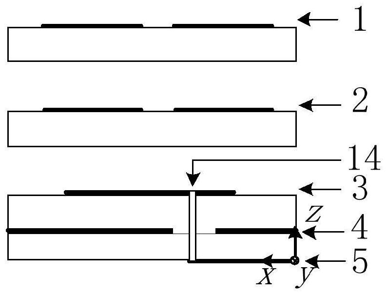
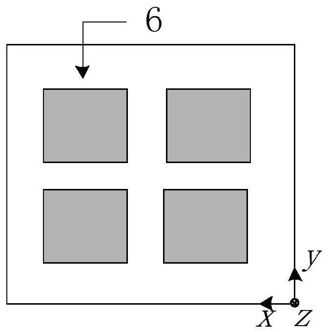
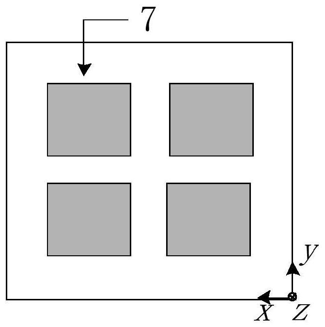
A broadband filter antenna, including a five-layer structure from top to bottom, the first layer structure includes a top layer patch structure, the second layer structure includes a bottom layer patch structure, the third layer structure includes two folded resonators, and the fourth layer structure includes The layer structure is a large metal formation with a pair of via holes, and the fifth layer structure includes a feed structure. The present invention solves the problem of large plane size and realizes the filtering performance of the antenna; it uses stacked multi-chips combined with resonators to generate three A reflection zero point to expand the working bandwidth of the antenna; the odd mode of the resonator produces a low-end radiation zero point, and the coupling between the top and bottom patch structures produces a high-end radiation zero point, thereby achieving the effect of improving the frequency selectivity on both sides of the working frequency band; by adjusting The impedance ratio of the first part and the second part of the folded resonator can adjust the low-end radiation zero point under the premise of maintaining the bandwidth; use the short-circuit stub loaded on the feeder to suppress the high-order mode out of the band, so as to improve the high-end antenna frequency purpose of out-of-band suppression.

Description

technical field [0001] The invention relates to the communication field, in particular to a broadband filter antenna. Background technique [0002] With the rapid development of wireless communication technology, the requirements for antenna integration and miniaturization are increasing, and antennas integrating multiple functions have become a development trend. In most wireless communication systems, there is always a bandpass filter behind the receiving antenna and the two are cascaded with each other. Therefore, integrating the two to form a filter antenna can effectively reduce the number of components and reduce the noise caused by the filter. loss, improving the matching of the passband edge and increasing the overall efficiency. [0003] For filter antennas, many design techniques have been reported. For example, an impedance converter can be used to cascade the antenna and filter to realize the fusion of filtering and antenna functions; or the antenna can be used...

Claims


Application Information

Patent Timeline
Patent Type & Authority Patents(China)
IPC IPC(8): H01Q1/38H01Q1/48H01Q1/50H01Q13/10H01Q13/08
CPCH01Q1/38H01Q1/48H01Q1/50H01Q13/08H01Q13/10
Inventor 施金张诚曹青华张威徐凯陈建新杨汶汶
Owner 南通大学技术转移中心有限公司
Why Eureka
Try Eureka