Supercharge Your Innovation With Domain-Expert AI Agents!

Radar sensor having a compact design

A technology of radar sensor and compact structure, applied in the field of radar sensor, can solve problems such as wind noise not allowing analysis, speed limit, etc.

Inactive Publication Date: 2008-08-13
ROBERT BOSCH GMBH
View PDF3 Cites 9 Cited by
  • Summary
  • Abstract
  • Description
  • Claims
  • Application Information

AI Technical Summary

Problems solved by technology

The maximum vehicle speed is severely restricted, since the wind noise that occurs does not allow analysis

Method used


Image

  • Radar sensor having a compact design
  • Radar sensor having a compact design

Examples


Embodiment Construction

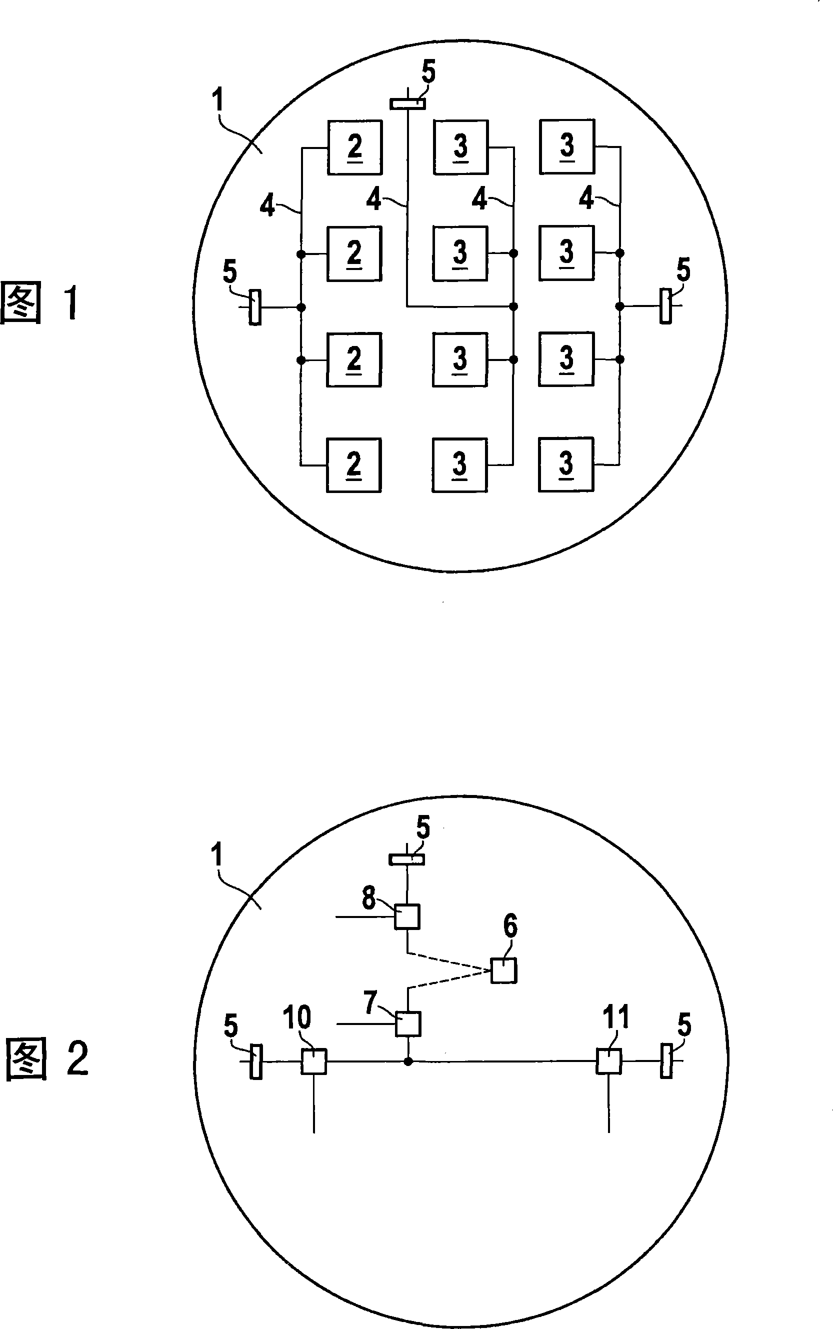
[0011] According to FIG. 1, the radar sensor according to the invention consists of a low-loss HF substrate 1 with a circular aperture. A transmitting array and at least one receiving array consisting of four patch units 2 are arranged on the front side of the HF substrate, which is represented as two receiving arrays in this embodiment, and each receiving array has four patch units 3 . The signal input to the array takes place via feed lines 4 which are also arranged on the HF substrate, for example as strip lines. Arrays of patch elements allow focusing beams in elevation, for example for blanking road echo interference. The feed ports of the three arrays are routed to the rear side of the RF substrate by means of radio-frequency coupling means 5, in the exemplary embodiment shown, slot couplers. The signal preparation for the transmission operation of the radar sensor and the signal evaluation for the reception operation of the radar sensor take place on the rear side of ...


PUM


Abstract

The invention relates to a radar sensor having a compact design, in which an emitting and receiving array (2, 3) are placed together with their feed lines (4) on the front side of an HF substrate. Active high-frequency modules (6, 7, 8, 10, 11) are placed on the rear side of the HF substrate (1). The coupling of the supply lines (4) to the high-frequency modules on the rear side is effected by high-frequency coupling devices (5).

Description

technical field [0001] The invention relates to a radar sensor of compact design. A microwave radar transceiver is known from DE 10300955 A1. Active circuit components are arranged there on the upper side of a substrate. The passive components are integrated in a multilayer structure in the substrate itself. Background technique [0002] The earlier application DE 102004059332.9 also discloses a radar transceiver in which an oscillator, a mixer and an antenna are arranged adjacent to one another in one plane on a single chip. [0003] Ultrasound-based systems are often used for distance sensors used as parking aids. Ultrasonic sensors reach their physical limits despite their ever-increasing range. Ranges of more than 4 meters are hardly achievable at reasonable cost. Furthermore, Doppler analysis (Doppler auswertung), ie, no direct velocity determination, is possible with the aid of ultrasound. The azimuth angle of the object is determined instantaneously by means of ...

Claims


Application Information

Patent Timeline
IPC IPC(8): G01S7/03
CPCG01S7/032G01S2013/9314
Inventor T・瓦尔特H・奥尔布里希D・施泰因布赫
Owner ROBERT BOSCH GMBH
Features
  • R&D
  • Intellectual Property
  • Life Sciences
  • Materials
  • Tech Scout
  • Unparalleled Data Quality
  • Higher Quality Content
  • 60% Fewer Hallucinations
Learn More