Capacitor motor and process for producing the same

A manufacturing method and motor technology, applied in the direction of electric components, electrical components, electromechanical devices, etc., can solve the problems of increased winding loss, reduced motor efficiency, and longer circumference, so as to reduce the magnetic flux density and improve the efficiency of the motor Effect

Inactive Publication Date: 2008-08-13
PANASONIC CORP
View PDF2 Cites 16 Cited by
  • Summary
  • Abstract
  • Description
  • Claims
  • Application Information

AI Technical Summary

Problems solved by technology

[0007] In the stator core, stator structure, and manufacturing method of such a conventional motor, there is a problem that since part or the whole of the teeth of the wound winding are formed of a dust core of magnetic powder with a low magnetic flux density, Therefore, in order to secure a predetermined amount of magnetic flux, it is necessary to have a larger cross-sectional area (the axial length of the teeth x the width dimension) than the laminated iron core. As a result, the circumference of the winding wound on the teeth becomes longer, and the The loss of consumption becomes larger, therefore, the efficiency of the motor decreases

Method used


Image

  • Capacitor motor and process for producing the same
  • Capacitor motor and process for producing the same
  • Capacitor motor and process for producing the same

Examples


Embodiment approach 1

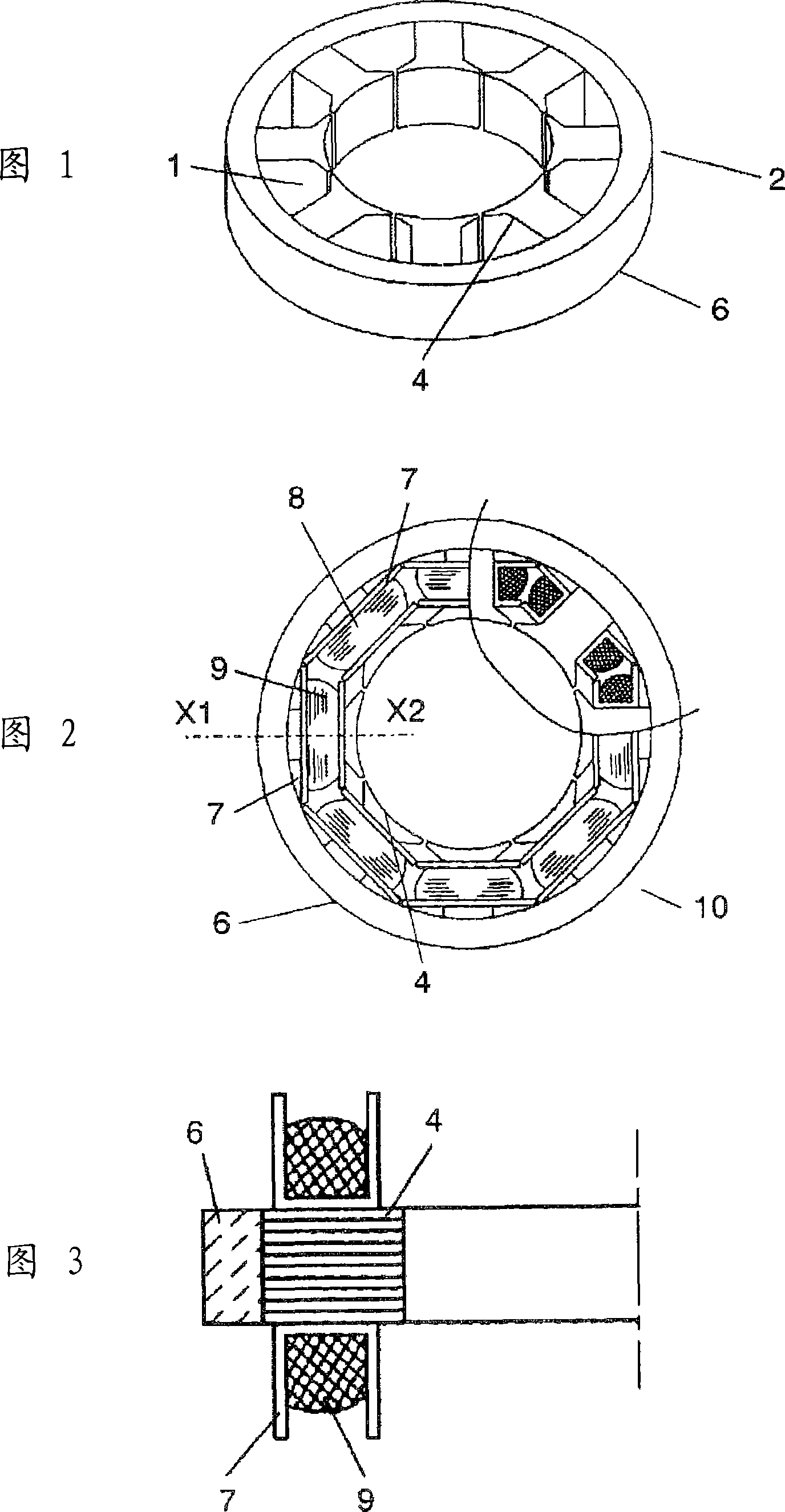
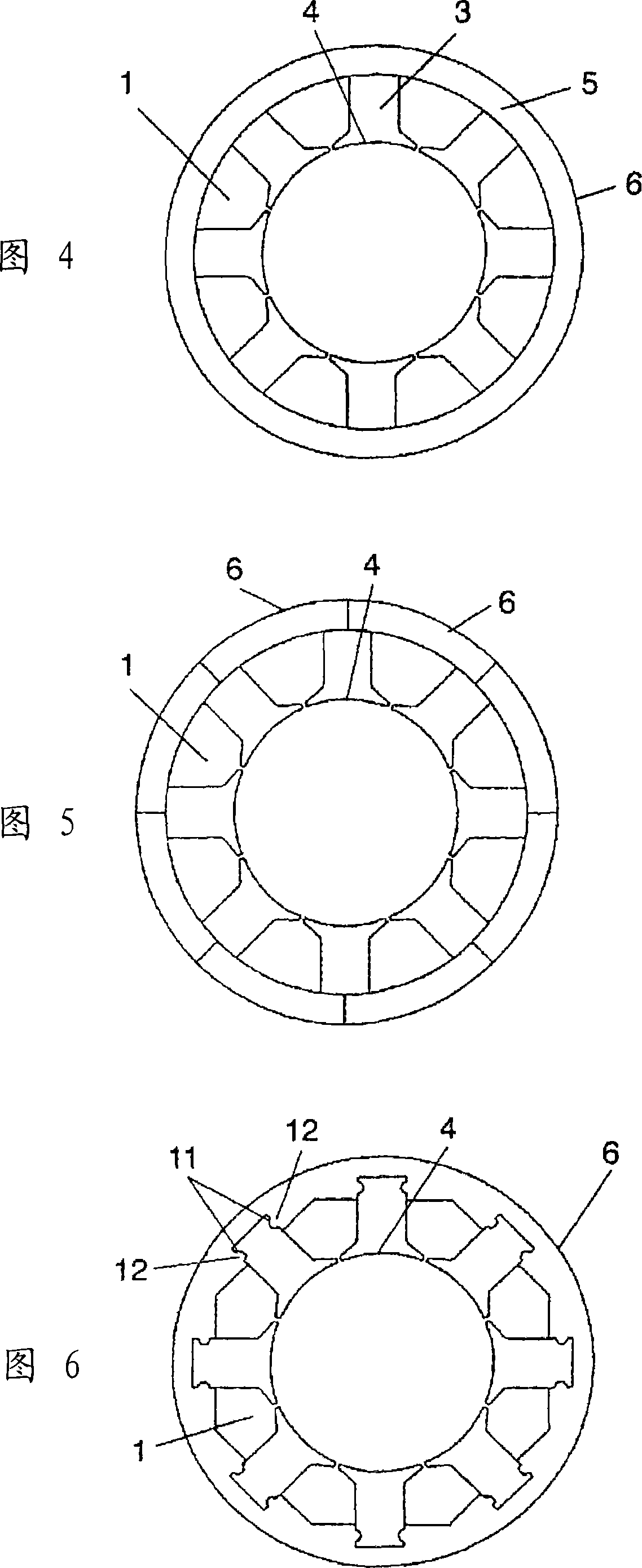
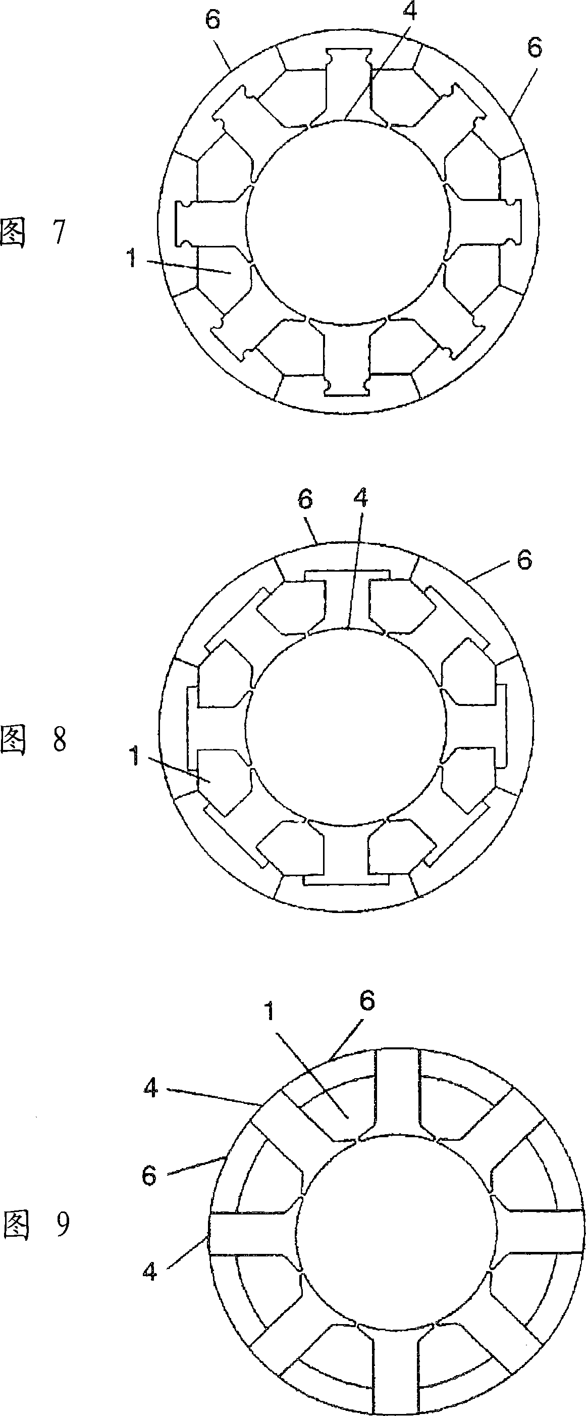
[0076] 1 to 10 show a stator of a capacitor motor according to this embodiment. As shown in these figures, the configuration of the capacitor motor of the present invention is that the stator core 2 having eight slots 1 is divided into eight first split iron core bodies 4 and second split iron core bodies 6, wherein the first split iron core body 6 One split iron core body 4 mainly forms each tooth portion 3; the second split iron core body 6 forms a magnetic circuit as a yoke portion on the outer peripheral side of the first split iron core body 4 and the slot 1. Each first split iron core body 4 is formed by punching and laminating electromagnetic steel sheets, and A-phase winding 8 or B-phase winding 9 wound on insulating bobbin 7 is attached to each tooth portion 3 . The first split iron core bodies 4 on which the A-phase winding 8 is attached and the first split iron core bodies 4 on which the B-phase winding 9 is attached are arranged alternately and annularly. The seco...

Embodiment approach 2

[0085] A second embodiment will be described based on FIGS. 11 to 13 . The same symbols are used for the same structural elements as those in Embodiment 1, and descriptions thereof are omitted.

[0086] In Fig. 11 and Fig. 12, the difference from Embodiment 1 is that the thickness N in the axial direction of the second split iron core body 6A formed by molding magnetic powder into a dust core of a predetermined shape is set to be smaller than that of punching and layering. The axial thickness L of the tooth portion 3 of the first split iron core body 4 of the laminated electrical steel plate, that is, the portion where the winding is mounted or wound is long. In addition, a rotor 14 having a rotor core 13 is arranged on the inner diameter portion of the stator core 2. The rotor core 13 is coaxial with the stator core 2 and is held to be freely rotatable. Its dimension M is the same as that of the first split core body The axial thickness L of 6A is the same.

[0087] In the ...

Embodiment approach 3

[0091] A third embodiment will be described with reference to FIGS. 14 and 15 . The same symbols are used for the same constituent elements as in Embodiments 1 and 2, and descriptions thereof are omitted.

[0092] As shown in FIGS. 14 and 15 , the difference from Embodiments 1 and 2 is the thickness in the axial direction of the second split iron core body 6A formed by molding magnetic powder into a dust core of a predetermined shape in Embodiment 2. , it is set to be longer than the axial thickness of the tooth part 3 of the first split iron core body 4 of the punched and laminated electromagnetic steel plate, that is, the part where the winding is installed or wound, and the following structural features are added on top of it, that is: for each second On the inside of the axial surface on the outer peripheral side of the split iron core body 4, on the inside of the axial surface of the front end portion on the same inner peripheral side, etc., the portion where the winding ...


PUM


Abstract

A capacitor motor which comprises a stator having stator iron cores and winding wires and a rotor having rotor iron cores, wherein the stator iron cores are composed of first divided iron cores having teeth and second divided iron cores forming magnetic paths for these first divided iron cores, and the winding wires are fitted to the teeth and housed in slots formed by the first divided iron cores and second divided iron cores. The first divided iron cores each is formed by superposing electromagnetic steel sheets formed by punching, while the second divided iron cores each is formed by molding magnetic particles into a given shape. The first divided iron cores are bonded to the second divided iron cores by a given means so that the teeth are radially formed along the outer periphery of the rotor iron cores.

Description

technical field [0001] The present invention relates to a capacitor motor and a manufacturing method thereof, which are separated and divided into the same number or more than the number of slots, and have a fixed iron core and a stator. The fixed iron core and stator are formed by stamping and laminating electromagnetic steel sheets The laminated iron core body and the powder magnetic core formed into a predetermined shape from magnetic powder are combined and integrated into one body. Background technique [0002] Conventionally, this type of motor has been known to have a structure in which an armature core (hereinafter referred to as: stator core) is divided into a plurality, each part is made of magnetic powder, and the stator teeth (hereinafter referred to as: tooth portion) are formed on the stator teeth (hereinafter referred to as: tooth portion). After the wire winding (hereinafter referred to as winding) is constructed, the tooth portion is integrally formed with a...

Claims


Application Information

Patent Timeline
Patent Type & Authority Applications(China)
IPC IPC(8): H02K1/16H02K1/02H02K1/18
CPCY10T29/49009H02K1/185H02K5/02H02K1/148H02K1/02
Inventor 西村茂树
Owner PANASONIC CORP
Why Eureka
Try Eureka