Welding head of electric spot welding machine

A technology of electric spot welding and welding head, applied in the direction of welding medium, electrode characteristics, welding equipment, etc., can solve the problems that affect the welding quality, welding head service life, unbalanced heat distribution on the welding surface, easy blackening and oxidation, etc. Long life, stable welding quality and fast heat dissipation

Inactive Publication Date: 2008-08-20
吴云龙
View PDF2 Cites 0 Cited by
  • Summary
  • Abstract
  • Description
  • Claims
  • Application Information

AI Technical Summary

Problems solved by technology

These welding heads of prior art are completely independent for two electrodes, and the tip (welding nozzle) position adopts the welding head of low ohm contact to have the advantage that the tip (welding tip) position does not produce electric spark, but also has its shortcoming: as Figure 4 As shown: because the welding surface of the tip of the welding head is a plane, and the heating area is only in the middle part of the left and right sides, the welding surface is much larger than the heating area, and the heat source diffuses from the middle to both sides to realize welding. Because of the time difference of heat conduction, the welding surface unbalanced heat distribution
And because the heat is concentrated in the middle of the welding head, the middle is easily blackened and oxidized and damaged, which affects the quality of welding and the service life of the welding head

Method used


Image

  • Welding head of electric spot welding machine
  • Welding head of electric spot welding machine
  • Welding head of electric spot welding machine

Examples


Embodiment Construction

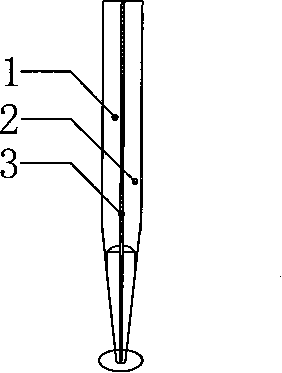
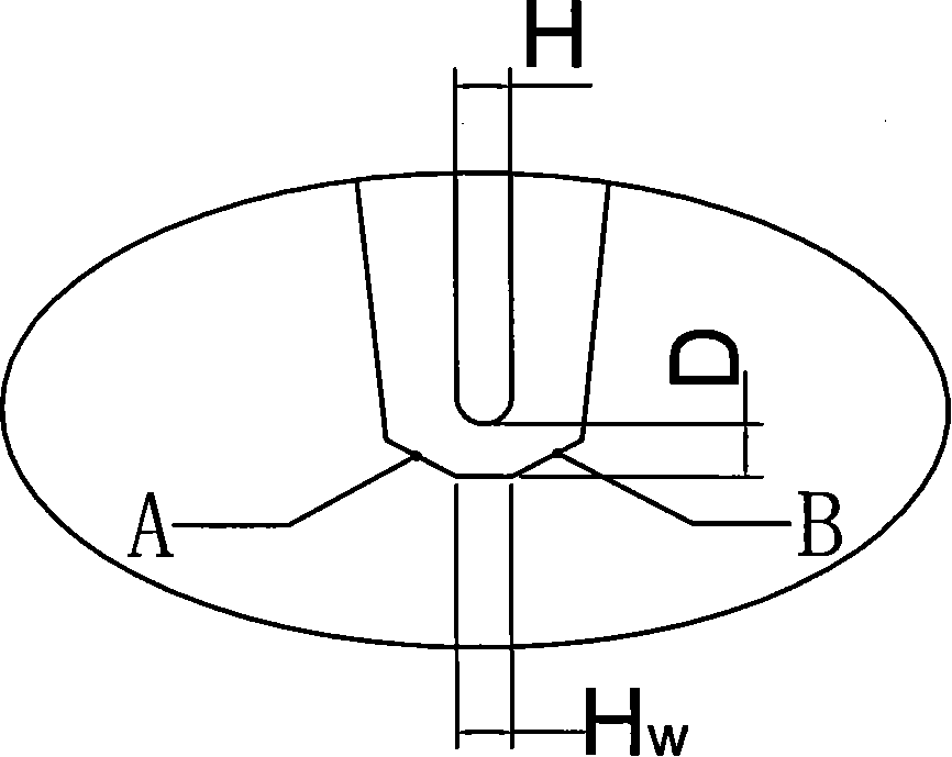
[0014] Referring to the accompanying drawings, the present invention includes two current leading ends (1, 2), and the front tip (tip) of the current leading end is connected, and it is characterized in that: the width (Hw) of the welding surface of the tip (tip) is the same as that of the two currents The width (H) of the connection surface of the leading part is equal, and the welding surface transitions with the two side chamfers.

[0015] The so-called connected specifically means continuous and uninterrupted. The chamfer can be selected between 30°-60°, generally 45°.

[0016] During the specific implementation of the present invention, a cylindrical refractory metal is cut longitudinally and equally divided into two current guiding parts (1, 2); D), the middle of which is fixed with insulating adhesive or other sticky insulators (3); then according to the needs of the welding workpiece, the welding surface is formed by means of cutting and grinding at the corresponding ...


PUM


Abstract

The invention discloses a welding head of electric spot welding machine. The welding head is a cylindrical metal bar with high melting point which is cleaved along the middle to form the leading parts of two electrodes. The bottom of the welding head has a reserved part heating element which is connected to form a heating element. The leading parts as well as the middle heating element form a current circuit. Because the material of the heating element is the same as the material of the leading parts and the cross-sectional area of the heating element is smaller than the cross-sectional area of the leading parts, the resistivity of the heating element is higher. When current flows along the heating element, high temperature due to the electric-thermal conversion accomplishes welding. A chamfer transition is arranged between the welding planar and the lateral face of the welding head. The area of the welding planar is near or equal to the area of the middle heating element. The heat energy is equably and intensively distributed on the hot side. The welding head has an advantage that: the welding head of spot welding has stable welding quality and long service life, and requires less maintenance.

Description

technical field [0001] The invention relates to a welding head, in particular to an electric spot welding head. Background technique [0002] The welding head of the electric spot welding machine is the most important consumable in the electric spot welding process. It consists of two electrodes (current leading ends) parallel to each other. The front end of the electrode is its tip, commonly known as the welding tip. CN03261340.7 patent discloses a kind of welding head in specification sheet is: " cuts and makes with the middle of a joint metal rod and the welding tip position is connected ". The welding head disclosed in Patent No. CN200520120768.9 is: "the tips of the two electrodes of the welding head are connected into one body". The welding heads disclosed in these two patents are all cut in the middle of a rod-shaped metal body to form two electrodes (current leading ends) and the tip (welding nozzle) is connected together as a heating area, and then the heating area...

Claims


Application Information

Patent Timeline
Patent Type & Authority Applications(China)
IPC IPC(8): B23K35/04B23K11/30
Inventor 吴云龙
Owner 吴云龙
Why Eureka
Try Eureka