Fabric dyeing and printing device

A fabric and atomization system technology, applied in the processing of textile materials, local processing of textile materials, textiles and papermaking, etc., can solve the problems of high production cost, high labor intensity of workers, low degree of automation, etc., and achieve the cost of printing and dyeing Low, improve printing and dyeing effect, high printing and dyeing efficiency

Inactive Publication Date: 2008-08-20
浙江宝通环保印染设备科技有限公司
View PDF0 Cites 8 Cited by
  • Summary
  • Abstract
  • Description
  • Claims
  • Application Information

AI Technical Summary

Problems solved by technology

The disadvantage of this kind of printing and dyeing equipment is that the products after printing and dyeing need to be processed by rinsing and other processes, which will generate a large amount of waste water, serious waste of dyes, long production cycle, low degree of automation, high labor intensity of workers, and high production costs.

Method used


Image

  • Fabric dyeing and printing device
  • Fabric dyeing and printing device

Examples


Embodiment 1

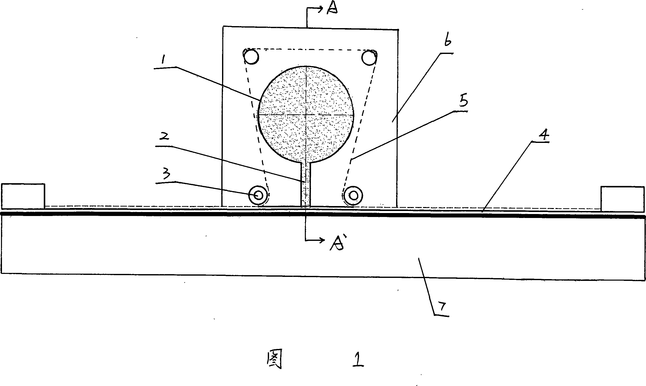
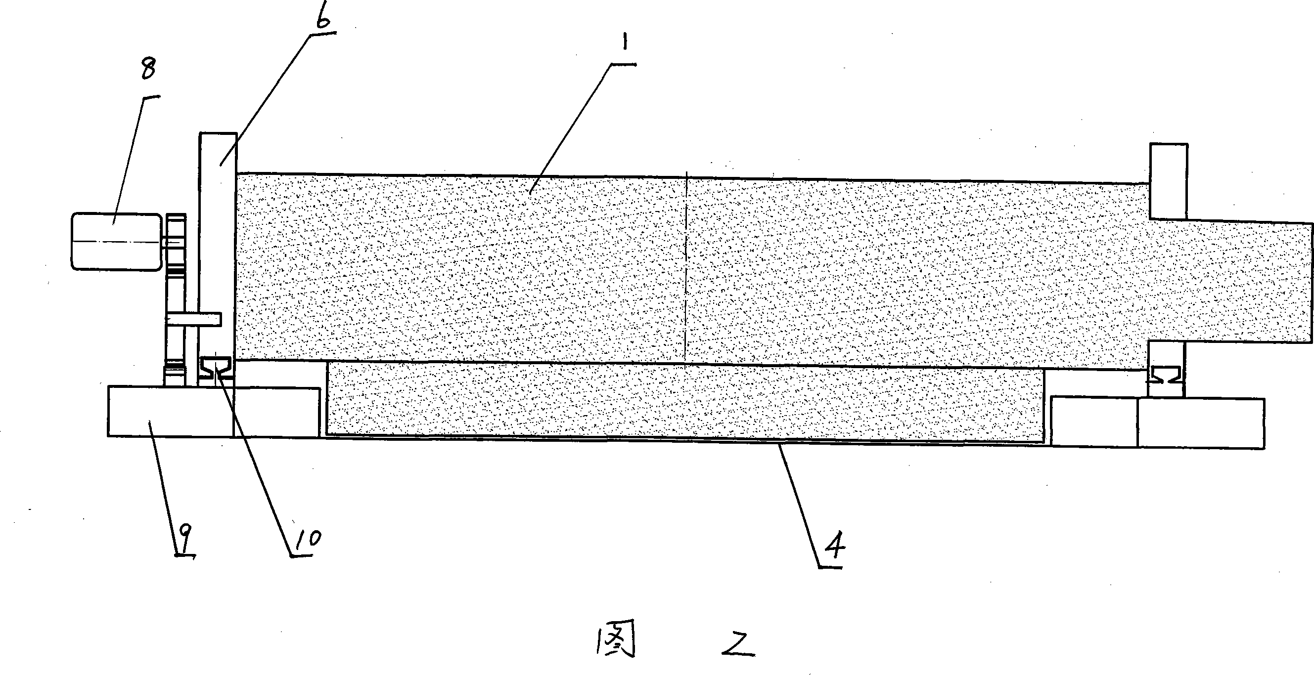
[0015] Example 1. Refer to Figure 1 and Figure 2. A fabric printing and dyeing device, comprising a frame 9, a power system and a transmission system, a fabric support is provided on the frame 1 or the transmission system, and the fabric support is made of a breathable material or is provided with air holes , the top and bottom of the fabric support are respectively provided with a vacuum adsorption chamber 7 and an atomization system; the vacuum adsorption chamber 7 is connected to a vacuum pipeline, and a vacuum pump is arranged on the vacuum pipeline; the atomization system includes an atomizer 1 and Dye channel 2; a pattern plate 4 is fixed on the frame 1 below the outlet of the dye channel 2, and the atomization system moves relative to the pattern plate 4 under the drive of the power system and transmission system.

Embodiment 2

[0016] Example 2. In the fabric printing and dyeing device described in Embodiment 1, a supporting wallboard 6 is also provided on the frame 9, and the supporting wallboard 6 slides on the frame 9 through the chute 10; There is a closed isolation film 5, and a pressure roller 3 is pressed on the closed isolation film 5. The atomization system is fixed on the support wallboard 6, and the pressure roller 3 is connected to the support wallboard 6 through a connecting shaft; The supporting wallboard 6, the atomization system and the pressure roller 3 move relative to the pattern plate 4 under the drive of the transmission system and the power system, and the pressure roller 3 cooperates with the atomization system to press the closed isolation film 5 during the movement.

Embodiment 3

[0017] Example 3. In the fabric printing and dyeing device described in Example 2, there are two pressure rollers 3, which are respectively symmetrically pressed on the closed isolation membranes 5 on the left and right sides of the atomization system.


PUM


Abstract

The invention relates to a fabric printing and dyeing device which includes a machine frame, a power system and a transmission system. The device is characterized in that: a fabric supporting piece is arranged on the machine frame or the transmission system. The fabric supporting piece is made by ventilating materials or is provided with a ventilating hole. The upward side and the downward side of the fabric supporting piece are respectively provided with a vacuum absorption cavity and an atomizing system. The vacuum absorption cavity is connected with a vacuum pipeline. A vacuum pump is arranged on the vacuum pipeline. The atomizing system includes an atomizer and a dye channel. A pattern templet is fixedly on the machine frame below the outlet of the dye channel. The atomizing system moves opposite to the pattern templet under the drive of the power system and the transmission system. The device of the invention utilizes vacuum subpressure absorption to print and dye atomized dyes on the fabric and has the advantages of simple and reasonable structure, low dyeing cost, high controllability on operation and high dyeing efficiency, being beneficial to improving the dyeing effect of the fabric. The color of the fabric after printing and dyeing is uniform and beautiful.

Description

technical field [0001] The invention relates to a dyeing and printing equipment for textiles. Background technique [0002] Most of the existing fabric printing and dyeing equipment is paste printing and dyeing equipment. When in use, the fabric is placed on the equipment to be flattened and fixed, and the printing and dyeing net is placed on it, and the dyes of various colors that have been adjusted into paste are applied to the corresponding color templates in sequence. On the fabric, the pasty color dye is pressed on the fabric with a magnetic roller or a scraper, and then the dyed fabric is cured, rinsed, dried and other post-processing procedures to complete the printing and dyeing. The disadvantage of this kind of printing and dyeing equipment is that the products after printing and dyeing need to be processed by rinsing and other processes, which will generate a large amount of waste water, serious waste of dyes, long production cycle, low degree of automation, high l...

Claims


Application Information

Patent Timeline
Patent Type & Authority Applications(China)
IPC IPC(8): D06B11/00D06B1/02D06B23/00D06B23/04
Inventor 张干
Owner 浙江宝通环保印染设备科技有限公司
Why Eureka
Try Eureka