Hydraulic pressure driven membrane pump with leakage compensation equipment

A diaphragm pump and diaphragm technology, applied to pumps with flexible working elements, mechanical equipment, pumps, etc., can solve problems such as suction limit

Inactive Publication Date: 2008-08-20
MILTON ROY EURO
View PDF1 Cites 7 Cited by
  • Summary
  • Abstract
  • Description
  • Claims
  • Application Information

AI Technical Summary

Problems solved by technology

This force that needs to be overcome limits the suction volume that the pump can deliver

Method used


Image

  • Hydraulic pressure driven membrane pump with leakage compensation equipment
  • Hydraulic pressure driven membrane pump with leakage compensation equipment

Examples


Embodiment Construction

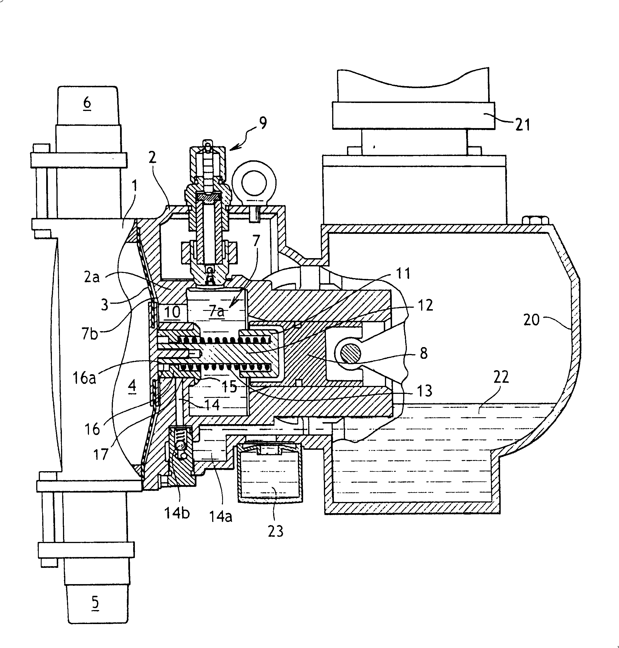
[0024] Typically, a hydraulically controlled diaphragm pump comprises a pump body consisting of two parts 1 and 2 with a perimeter of a diaphragm 3 sandwiched between them.

[0025] The diaphragm and part 1 of the body together define a pump chamber 4 in which both the suction conduit 5 and the delivery conduit 6 terminate and are fitted with non-return valves (not shown).

[0026] The diaphragm and part 2 of the body together define a cavity 7 filled with hydraulic fluid which can be cyclically displaced forwards (to the left of the figure) or backwards by a reciprocatingly driven piston 8 . This provides hydraulic control over the change in volume of the pump chamber 4 .

[0027] The chamber 7 is also usually fitted with a safety valve 9 for limiting the delivery pressure to a predetermined safety value and which is usually used in conjunction with means for evacuating the control fluid.

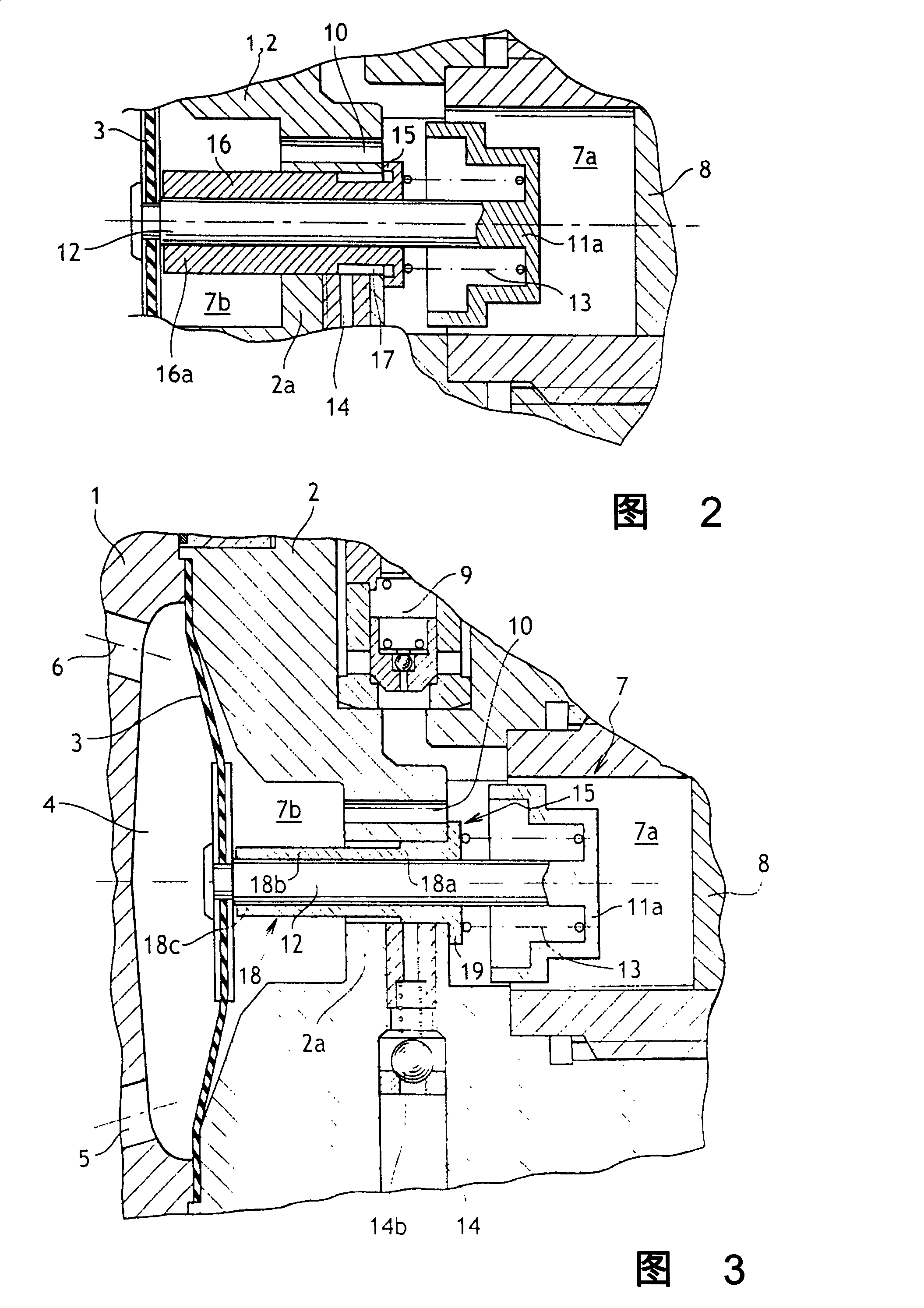
[0028] exist figure 1 , it should be observed that cavity 7 has two parts. The gene...


PUM


Abstract

The invention provides a diaphragm pump (3) which comprises a hydraulic control chamber (7) which is arranged between a piston (8) which carries out a reciprocating movement and a diaphragm (3) in pump bodies (1, 2). The diaphragm pump comprises a device used for compensating the leakage of the hydraulic chamber (7); the device comprises a supplementary duct (14) which is provided with an opening which faces into the hydraulic chamber by a normal-close compensation valve (15) which can be driven to an opening position by the diaphragm (3). The diaphragm pump (3) is characterized in that the compensation valve (15) is driven by the diaphragm (3) of the free end (16a) of the rod (16) which pushes against and controls the valve; the diaphragm (3) is subject to the force of a pumping and suction booster spring (13); the spring (13) cooperates with the valve (15) and pushes back the free end (16a) of the control rod (16) to the diaphragm (3) and returns to a closed position; the spring (13) is matched with the valve (15) so as to form a movable component which can be moved without the deformation of the diaphragm (3) during the pumping and suction stroke.

Description

technical field [0001] The present invention relates to a hydraulically actuated diaphragm pump whose diaphragm is protected in the event of hydraulic fluid leakage from the drive chamber. Background technique [0002] Suction overstroke is caused by lack of fluid in the hydraulic chamber used to drive the diaphragm. In fact, in some types of pumps, this overstroke does not take place because, at the end of the suction stroke, the diaphragm bears against a surface intended to limit its stroke. This can lead to cavitation in the hydraulic chamber and, in any event, a reduction in the volumetric volume of the pump. In some pumps, the suction stroke of the diaphragm does not have any mechanical limit, overstroke not only reduces performance, but also causes excessive fatigue and deformation of the diaphragm, which can jeopardize its life length. [0003] Transmission overtravel is caused by excess fluid in the hydraulic chamber used to drive the diaphragm. This can occur, fo...

Claims


Application Information

Patent Timeline
Patent Type & Authority Applications(China)
IPC IPC(8): F04B43/06F04B9/06
Inventor G·斯鲍德
Owner MILTON ROY EURO
Why Eureka
Try Eureka