Redundant electrohydraulic servo-controlling system

An electro-hydraulic servo and control system technology, applied in the field of electro-hydraulic servo systems, can solve problems such as insufficient flow of electro-hydraulic servo control systems, and achieve the effects of reducing energy consumption, increasing safety, and improving responsiveness

Inactive Publication Date: 2008-08-20
TAIYUAN UNIV OF TECH
View PDF0 Cites 38 Cited by
  • Summary
  • Abstract
  • Description
  • Claims
  • Application Information

AI Technical Summary

Problems solved by technology

[0004] Based on the deficiencies of the above-mentioned existing electro-hydraulic servo control system, the purpose of the present invention is to provide a redundant electro-hydraulic servo control

Method used


Image

  • Redundant electrohydraulic servo-controlling system
  • Redundant electrohydraulic servo-controlling system
  • Redundant electrohydraulic servo-controlling system

Examples


Embodiment 1

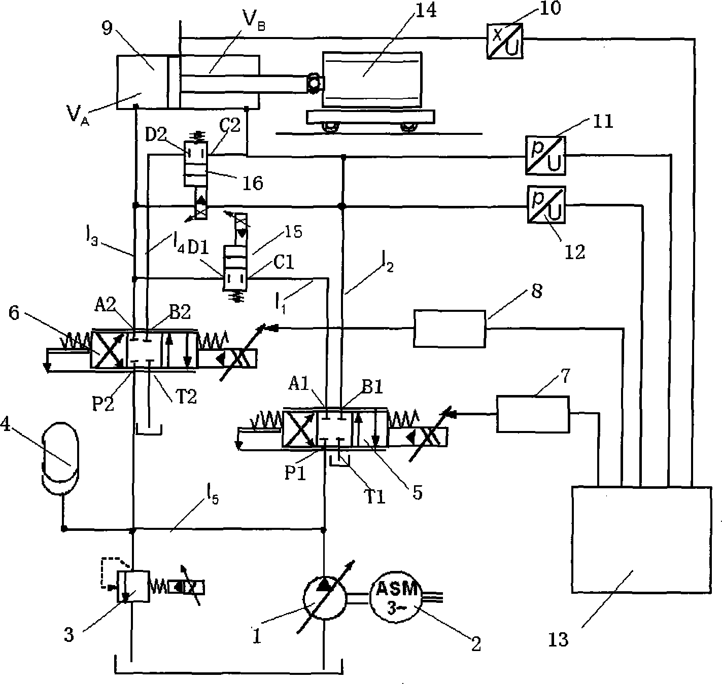
[0019] Such as figure 1 , the hydraulic pump 1, the motor 2, the relief valve 3 and the accumulator 4 constitute the hydraulic oil source, the output shaft of the motor 2 is connected with the input shaft of the hydraulic pump 1 through a coupling, and the oil inlet of the hydraulic pump 1 is connected through a pipeline Connected to the oil tank, the oil outlet of the hydraulic pump 1 passes through the fifth hydraulic line l 5 Output, as the output of the oil source, the oil inlet of the relief valve 3 passes through the fifth hydraulic line l 5 It is connected to the oil outlet of the hydraulic pump 1, the oil return port of the relief valve 3 is connected to the oil tank, and the oil port of the accumulator 4 passes through the fifth hydraulic pipeline l 5 Connected to the output port of the oil source; the first oil outlet A1 of the servo valve I5 passes through the first hydraulic line l 1 , two-position two-way solenoid valve I15, the third hydraulic pipeline l 3 It ...

Embodiment 2

[0022] Such as figure 1 , the connection mode and structural principle of this embodiment are the same as those in Embodiment 1, the two-position two-way solenoid valve I15 and the two-position two-way solenoid valve II16 are simultaneously connected, and the maximum movement speed of the load 14 in the left and right directions in the figure Respectively reach twice the single servo valve control. Realize high-speed response control to the load.

Embodiment 3

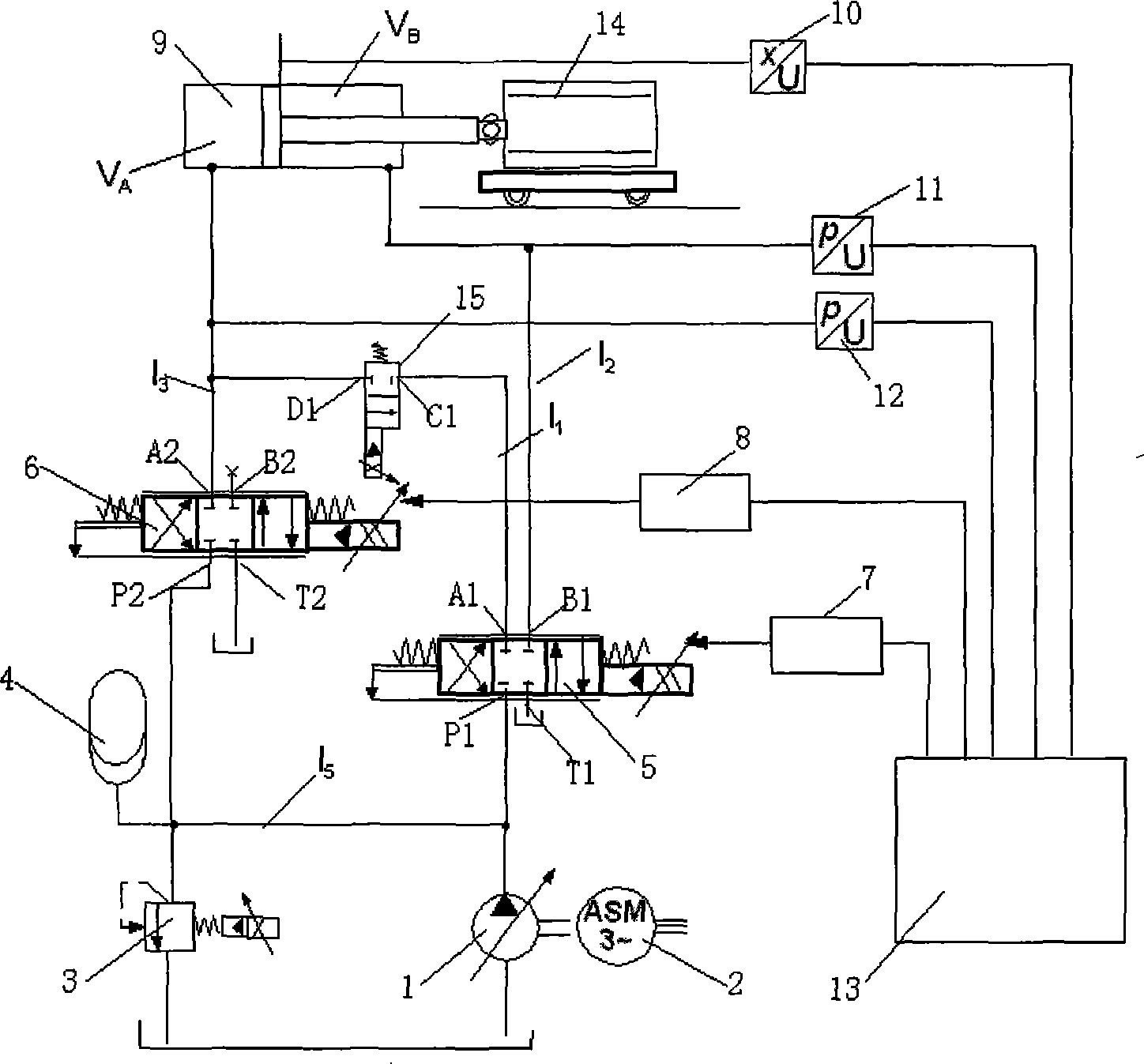
[0024] Such as figure 2 , connect the two-position two-way solenoid valve I15, and the hydraulic actuator 9 moves in one direction (moving to the right in the figure). Double servo valve I5 and servo valve II6 are used to supply oil, while the hydraulic actuator moves in the other direction (moving to the right in the figure). middle to left movement) adopts single servo valve I5 to supply oil. This method is used to increase the one-way flow rate of the hydraulic actuator 9 and is suitable for balancing the movement speed of the asymmetric hydraulic actuator 9 in two directions.


PUM


Abstract

The invention provides a redundancy electro hydraulic servo system, which is an electro hydraulic servo system controlled by a dual-flux servo valve or a dual-servo proportion valve. By a two-position two-way electromagnetic valve, a controllable parallel connection between the two valves is realized, the dynamic adjustment of the control scheme is realized, and the realization of the load motion speed and index is achieved, thus achieving the objects of high efficiency and energy-saving control and simultaneously improving the reliability of the system.

Description

technical field [0001] The invention relates to an electro-hydraulic servo control system, in particular to an electro-hydraulic servo system controlled by a dual-flow servo valve or a servo proportional valve. technical background [0002] An existing independent electro-hydraulic servo system uses a servo valve or proportional valve as its key control element. In general, when the design response speed of a servo valve or proportional valve reaches a certain level, its design output flow will gradually decrease. If the actual system requires both a high response speed and a large output flow, the existing hydraulic servo control technology cannot meet the requirements. Its requirements, at this time must reduce the index requirements of the actual system or give up the hydraulic servo control scheme. Although the indicators of foreign products (mainly American, German, and Japanese products on the market) are much higher than those of domestic products, they still cannot ...

Claims


Application Information

Patent Timeline
IPC IPC(8): F15B13/02F15B13/06
Inventor 权龙许小庆
Owner TAIYUAN UNIV OF TECH
Why Eureka
Try Eureka