

Ultra-wideband filter based on simplified left hand transmission line structure
A technology of ultra-wideband filter and left-handed transmission line, applied in waveguide devices, electrical components, circuits, etc., to achieve good out-of-band performance, low precision requirements, and small in-band insertion loss
- Summary
- Abstract
- Description
- Claims
- Application Information
AI Technical Summary
Problems solved by technology
Method used
Image

Examples
Embodiment 1
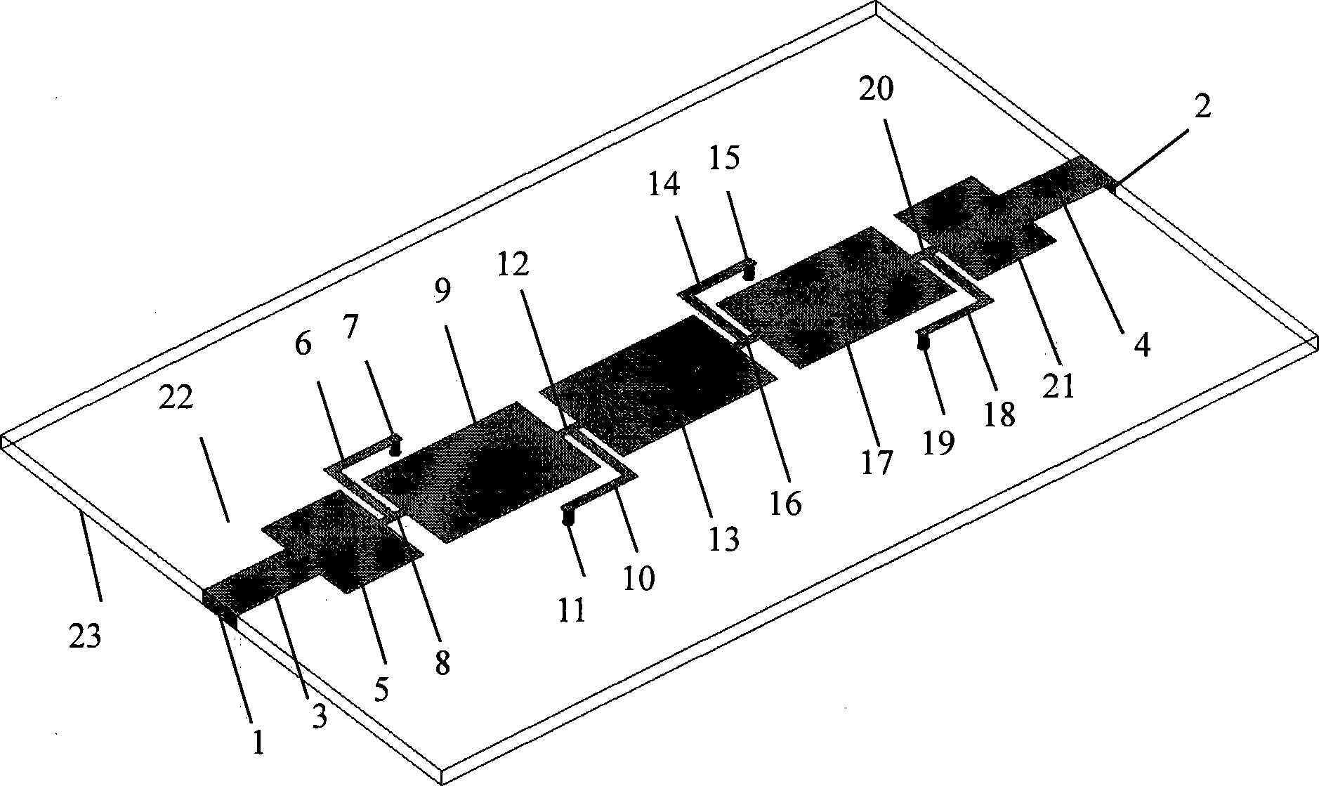
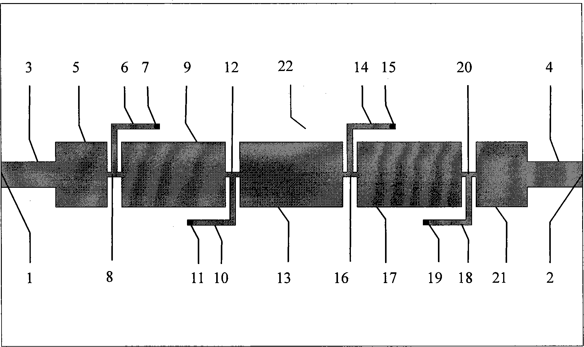
[0018] The technical solutions of the present invention will be described in detail through specific embodiments below in conjunction with the accompanying drawings. Example 1: first refer to Figure 1~2 The structure diagram of the UWB bandpass filter utilizing the simplified left-handed transmission line structure of the present invention is described.
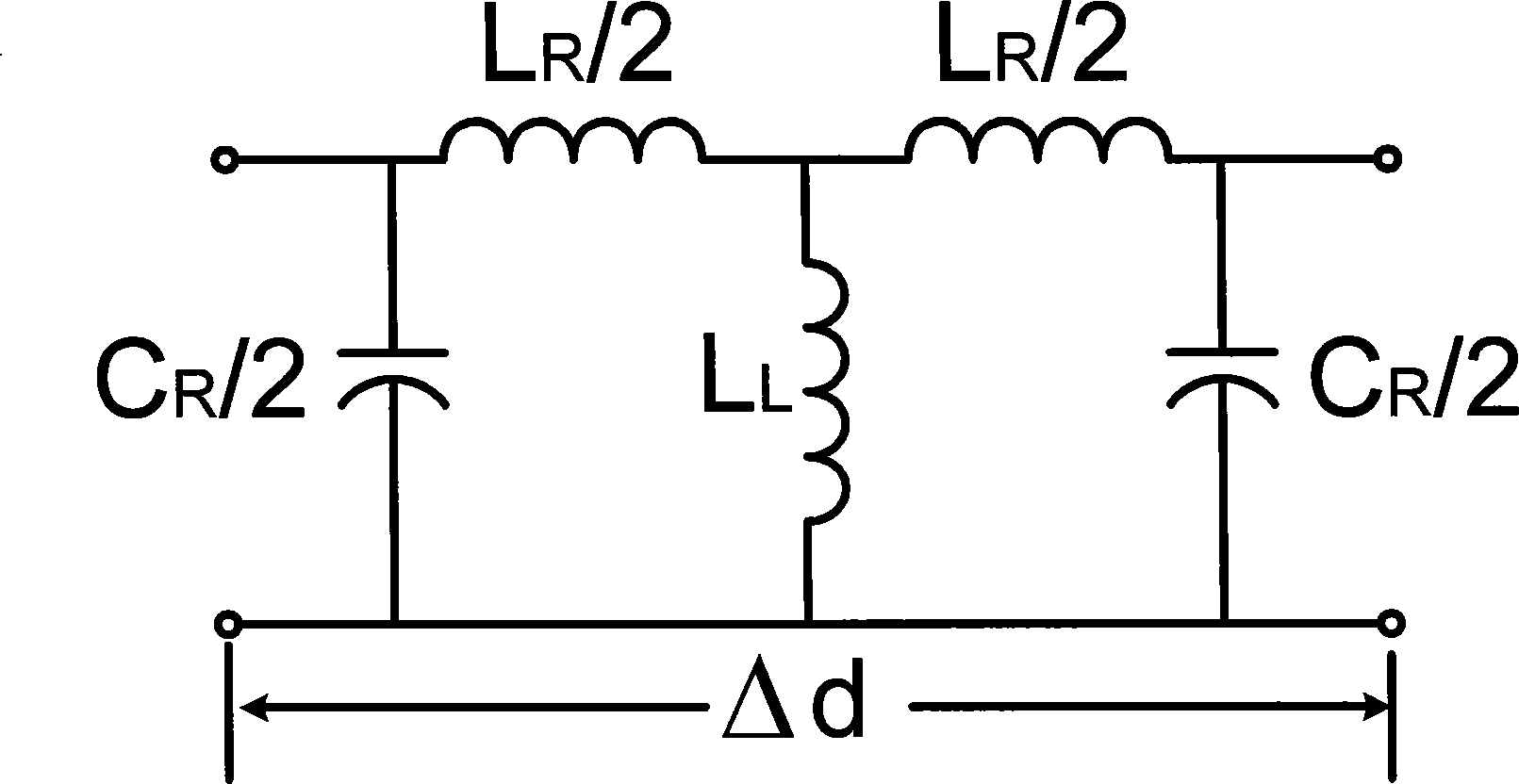
[0019] The ultra-wideband filter utilizing a simplified left-handed transmission line structure in the present invention includes an input port 1, an output port 2 and at least one simplified left-handed transmission line structure unit on a PCB. The input end is connected to the first microstrip line structural unit through a 50-ohm microstrip line 3 , and the output end is connected to the last microstrip line structural unit through a 50-ohm microstrip line 4 . Each microstrip line structure unit is composed of series inductors, parallel capacitors and parallel inductors. The equivalent circuit model is shown in image ...
Embodiment 2
[0022] Embodiment 2: Referring to FIG. 8 , the grounded short microstrip line stubs of the filter of the present invention can have many different distribution forms. The grounded narrow microstrip transmission line can be distributed on the same side or above and below the main transmission line. It can be a straight line, a broken line, or other shapes. The curved segment of the zigzag type can be directed towards the input or towards the output. Other than that, the rest are the same as in Example 1.
PUM
 Abstract
Description
Claims
Application Information