
Method for denoising bump-scrape acoustic emission signal based on discrete fraction cosine transform

A technology of acoustic emission signal and cosine transform, which is applied in the field of noise reduction of rubbing acoustic emission signal. The effect of acoustic emission signals

Inactive Publication Date: 2008-08-27
邓艾东
View PDF0 Cites 14 Cited by
  • Summary
  • Abstract
  • Description
  • Claims
  • Application Information

AI Technical Summary

Problems solved by technology

However, due to the diversity and transient nature of acoustic emission sources and the complexity of noise sources, the use of DCT for acoustic emission signal noise reduction processing still cannot achieve satisfactory results.

Method used


Image

  • Method for denoising bump-scrape acoustic emission signal based on discrete fraction cosine transform
  • Method for denoising bump-scrape acoustic emission signal based on discrete fraction cosine transform
  • Method for denoising bump-scrape acoustic emission signal based on discrete fraction cosine transform

Examples


Embodiment Construction

[0031] The technical solutions of the present invention will be further described below in conjunction with the drawings and embodiments.

[0032] 1. Acoustic emission signal extraction and preprocessing

[0033] 1. Acoustic emission signal extraction

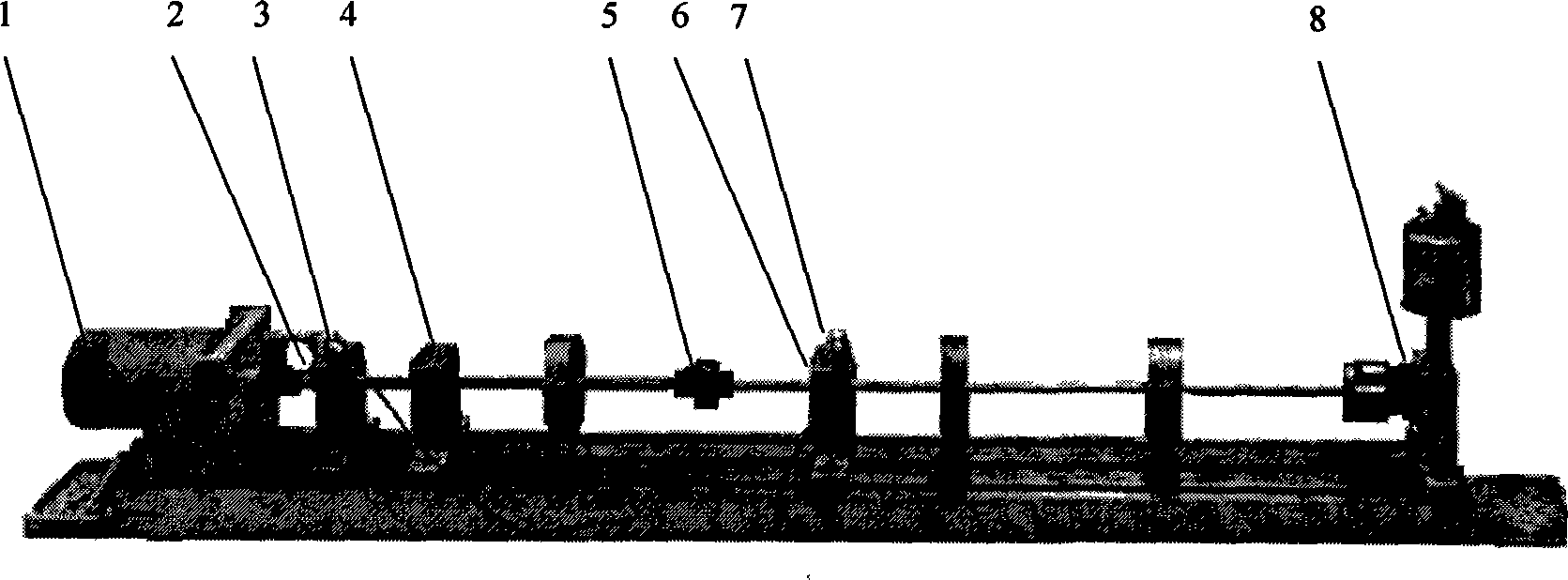
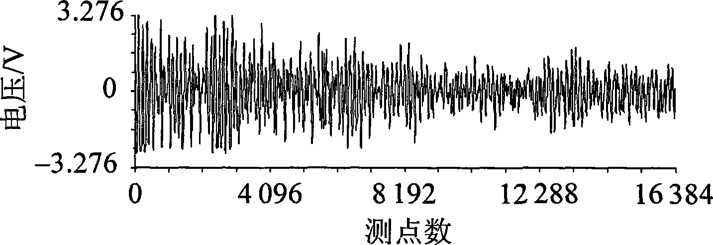
[0034] This test uses a 3-support 2-span rotor system, such as figure 1 shown. The three bearings, that is, the first bearing 2 , the second bearing 6 and the third bearing 8 are all hydrodynamic lubricated sliding bearings, the friction point 4 is close to the motor 1 , and the first acoustic emission sensor 3 is close to the friction point 4 . The second acoustic emission sensor 7 is located at the other end of the coupling 5 . The acoustic emission signal waveforms extracted by the first acoustic emission sensor 3 and the second acoustic emission sensor 7 can be used to analyze the attenuation of acoustic signal propagation and the signal distortion after coupling through a discontinuous medium. In the experiment, the sa...


PUM


Abstract

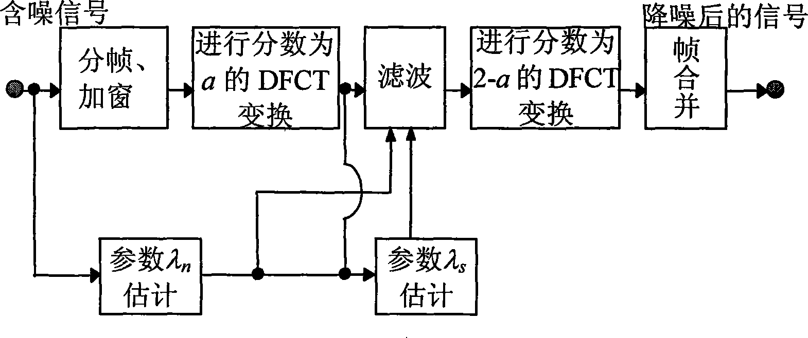
The invention relates to a rubbing sound emission signal denoising method based on discrete fraction cosine transform. The invention comprises the technical proposal that: a sound emission signal is extracted from an emission sensor of a friction point and superimposed with noise; the signal comprising noise is sampled, quantized and subframed and added with windows to obtain a discrete time sequence; the sequence is carried out discrete fraction Fourier transform with the fraction a to obtain F(k), then the signal after being filtered is carried out the discrete fraction Fourier transform with the fraction 2-a and the combination of frames; the signal after being denoised is output. The rubbing sound emission signal denoising method solves the disadvantages that a sound emission source has diversity, transient property and a noise source has complexity and can not gain satisfactory effect. The rubbing sound emission signal denoising method can obtain good denoising effect to the rubbing sound emission signal under the environment of a plurality of nonstationary noise, strengthen the sound emission signal, has robustness to the diversity and transient property of the sound emission source and the complexity of the noise source, effectively solves the problem of the large calculation amount in the prior method and has wide applicability.

Description

technical field [0001] The invention relates to a noise reduction method for rubbing acoustic emission signals, in particular to a noise reduction method for rubbing acoustic emission signals based on discrete fractional cosine transform. Background technique [0002] Acoustic emission technology is a way and method for rubbing fault detection of rotating machinery. However, the noise interference problem faced by acoustic emission technology is very serious, especially the multi-source strong noise pollution brought by the operating environment of rotating machinery, which makes the acoustic emission signal submerged in the noise and cannot reflect the true state of the equipment. Extracting and identifying useful acoustic signals from noise is the core content of the application of acoustic emission technology, and it is also the technical bottleneck for most current acoustic emission technology detection that cannot be effectively performed. Therefore, noise reduction pr...

Claims


Application Information

Patent Timeline
Patent Type & Authority Applications(China)
IPC IPC(8): G01M19/00G01H17/00G06F17/14G01M99/00
Inventor 邓艾东包永强傅行军赵力魏昕
Owner 邓艾东
Learn More