Special purpose device for measuring superconducting line joint resistance

A special device and superconducting wire technology, applied in the field of superconductivity, can solve the problems of affecting the measurement accuracy, poor shielding effect, affecting the attenuation magnetic field, etc., to achieve the effect of reducing the cost of the device, reducing the amount of volatilization, and improving the reliability of measurement

Inactive Publication Date: 2008-08-27
TSINGHUA UNIV
View PDF0 Cites 21 Cited by
  • Summary
  • Abstract
  • Description
  • Claims
  • Application Information

AI Technical Summary

Problems solved by technology

In addition, a background magnetic field of a certain strength is required in the process of measuring the resistance of superconducting joints. If the background magnet is placed in an inappropriate position or the shielding effect is not good, it will affect the attenuated magnetic field generated by the superconducting joint sample, thereby affecting the measurement accuracy.

Method used


Image

  • Special purpose device for measuring superconducting line joint resistance
  • Special purpose device for measuring superconducting line joint resistance
  • Special purpose device for measuring superconducting line joint resistance

Examples


Embodiment Construction

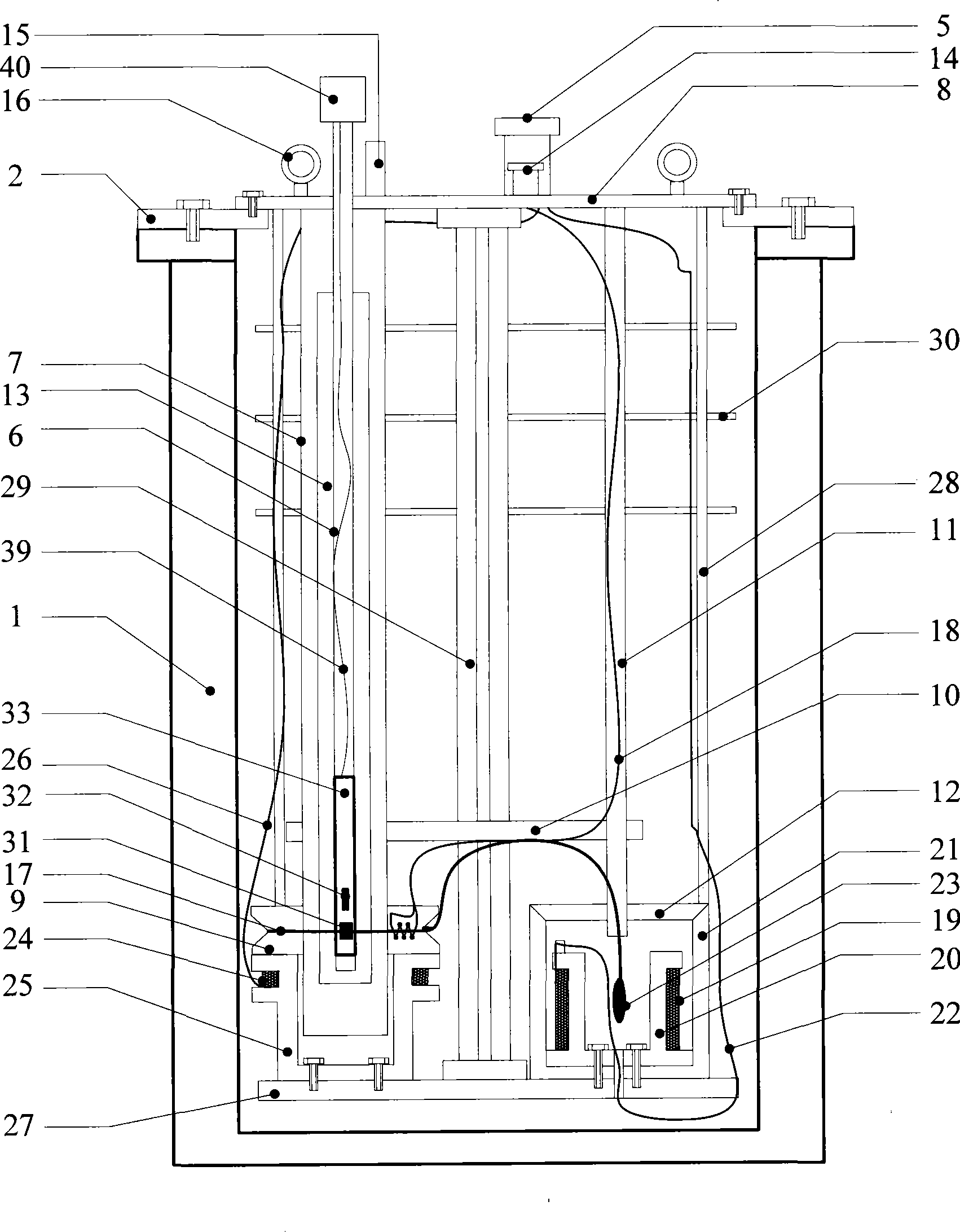
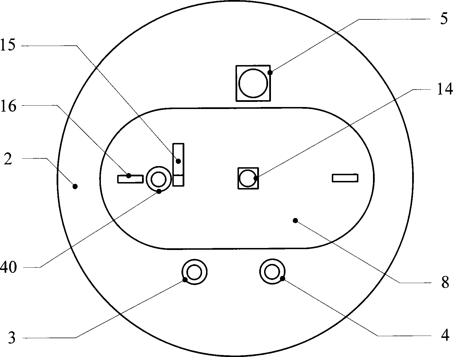
[0016] The principle and specific implementation of the present invention will be described below in conjunction with the accompanying drawings. Figure 1A It is a schematic diagram of the overall structure of a special device for measuring the resistance of superconducting wire joints. The magnetic field measurement unit constitutes.

[0017] Each unit of the device is assembled according to the following steps:

[0018] (1) The background magnet unit and the excitation magnet unit are respectively fixed on the bottom plate 27 of the coupling frame unit with epoxy screws;

[0019] (2) Connect the entire coupling frame unit with the low-temperature Dewar flange 2, and then place the stainless steel low-temperature Dewar 1 as a whole, and fix the upper opening of the low-temperature Dewar flange 2 and the stainless steel low-temperature Dewar 1 with bolts;

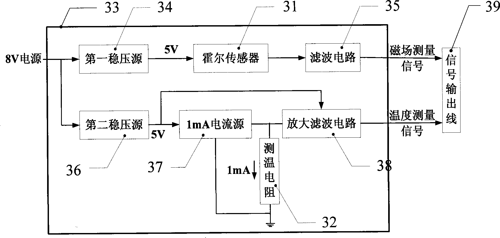
[0020] (3) Put the measurement circuit board 33 of the attenuation magnetic field measurement unit into the bottom of th...


PUM


Abstract

The present invention discloses a specialized device for measuring the resistance of a superconducting line joint, comprising a low temperature Dewar unit, a room temperature tube unit, a background magnet unit, an excitation magnet unit, a linkage frame unit, a weakening magnetic field measuring unit, etc. The specialized device has the advantages that only the room temperature tube is required to be moved out from the low temperature Dewar via a guide rail when a sample loop of the measured superconducting line joint is replaced, so that the volatilization amount of the liquid helium in an experimental process is reduced. The background magnet is positioned on the lateral side of a Hall element which measures the weakening magnetic field of the sample loop of the superconducting line joint. Compared with being positioned at the lower side of the Hall element, the background magnet positioned at the lateral side of the Hall element reduces the influence of the background magnet to the fact that the Hall element measures the weakening magnetic field generated by the sample loop of the superconducting joint. With the room temperature tube technical, the Hall element is arranged inside the room temperature tube, namely a normal temperature Hall sensor measures the weakening magnetic field of the sample loop of the superconducting joint. The cost of the device is reduced and the reliability of the measurement is improved.

Description

technical field [0001] The invention belongs to the technical field of superconductivity, and relates to a special device for measuring the joint resistance of superconducting wires. Background technique [0002] The resistance of the superconducting wire in the superconducting state is close to zero, and it can flow a larger current than the normal temperature conductor, and its application is becoming more and more extensive. However, in the manufacturing process of large and medium-sized superconducting coils, a large amount of superconducting wire is used. Due to the requirements and restrictions of the length of the superconducting wire supplied by the manufacturer or the winding process of the superconducting coil, it is difficult to complete the winding of the coil with a complete superconducting wire. . Therefore, there are some forms of superconducting joints in the structure of large and medium-sized superconducting coils. At this time, the current carrying capaci...

Claims


Application Information

Patent Timeline
Patent Type & Authority Applications(China)
IPC IPC(8): G01R27/02G01R33/07
Inventor 毕大强蒋晓华郭伟
Owner TSINGHUA UNIV
Why Eureka
Try Eureka