Left, right, right three-section type spiral winding method and structure of energy-saving filament

A winding method, a three-stage technology, applied to the right, the winding structure of the filament, the right three-stage spiral winding method and structure, and the left field of the energy-saving filament. Problems such as twisted rings and electronic powder falling off when touched, achieve the effect of low production cost, high pass rate, and easy operation

Inactive Publication Date: 2010-10-13
湖州太箭照明有限公司
View PDF2 Cites 0 Cited by
  • Summary
  • Abstract
  • Description
  • Claims
  • Application Information

AI Technical Summary

Problems solved by technology

The problem with this winding method is that the coils of the filament are easily twisted and twisted after stretching, resulting in a short circuit of the filament, which seriously affects the qualified rate of the stretched filament, and because the filament of the stretched loop requires a lot of manual repairs, the labor cost is high, and at the same time The electronic powder coated in the filament spiral is easy to be touched and falls off during repair, which directly affects the life of the lamp tube

Method used


Image

  • Left, right, right three-section type spiral winding method and structure of energy-saving filament
  • Left, right, right three-section type spiral winding method and structure of energy-saving filament
  • Left, right, right three-section type spiral winding method and structure of energy-saving filament

Examples


Embodiment Construction

[0013] The present invention will be further described below with reference to the accompanying drawings and embodiments.

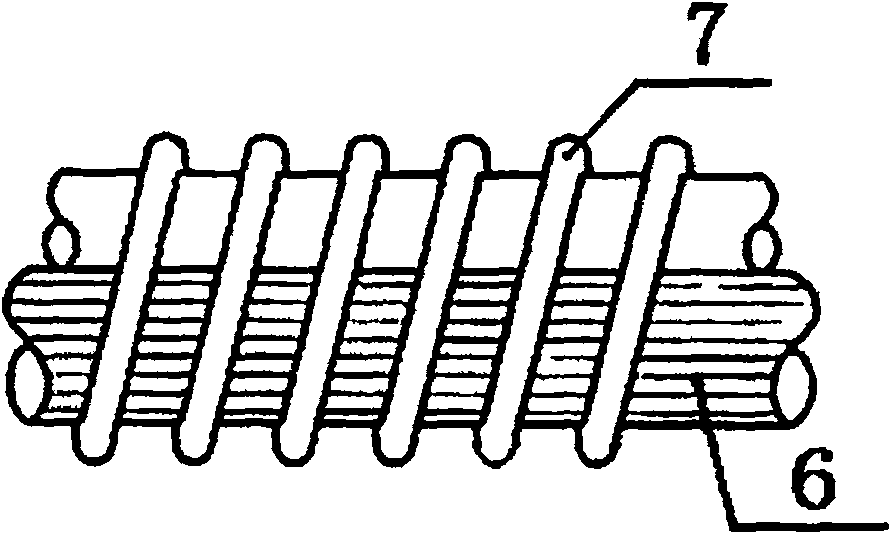
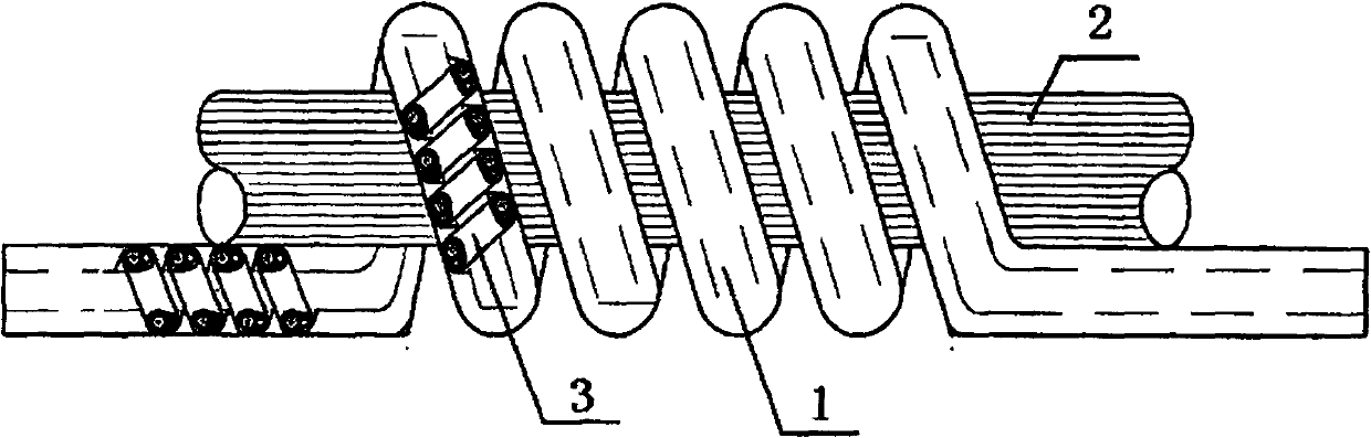
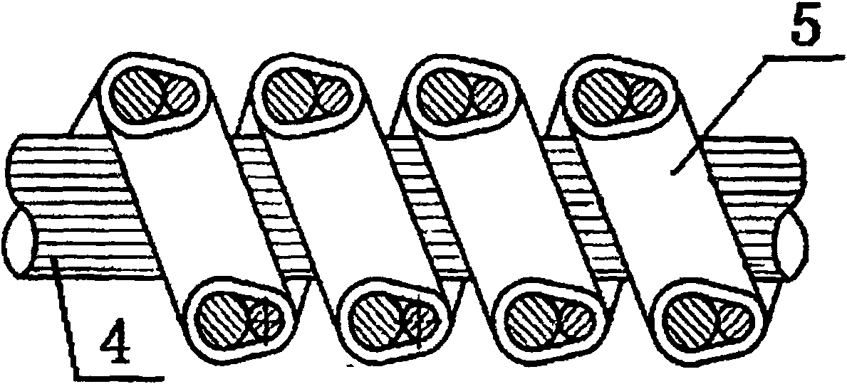
[0014] The embodiment of the present invention: it comprises a helical filament body 1, and the filament body 1 is composed of a mandrel 2 and a filament secondary winding body 3 wound around the periphery of the mandrel 2, as shown in the attached figure 1 The filament secondary winding body 3 is composed of a molybdenum core wire 4 and a filament primary winding body 5 wound around the periphery of the molybdenum core wire 4, as shown in the attached figure 2 As shown; the primary winding body 5 of the filament is composed of a molybdenum core wire 6 and a tungsten wire 7 wound around the periphery of the molybdenum core wire 6, as shown in the attached image 3 shown. The primary winding body 5 of the filament is wound on the molybdenum core wire 4 in a right helical manner, the secondary winding body 3 of the filament is wound on the mandrel 2 in a ...


PUM


Abstract

The invention discloses a left-right-right three-stage helical winding method and a left-right-right three-stage helical winding structure for an energy saving filament. The structure comprises a helical filament body (1), wherein, the filament body (1) consists of a mandrel (2) and a filament secondary winding body (3) which is wound on the periphery of the mandrel (2); the filament secondary winding body (3) consists of a molybdenum core wire (4) and a filament primary winding body (5) which is wound on the periphery of the molybdenum core wire (4); the filament primary winding body (5) consists of a molybdenum core wire (6) and a tungsten filament (7) which is wound on the periphery of the molybdenum core wire (6); the tungsten filament (7) is wound on the molybdenum core wire (6) by means of left screw; the filament primary winding body (5) is wound on the molybdenum core wire (4) by means of right screw; the filament secondary winding body (3) is wound on the mandrel (2) by meansof right screw. The filament adopts the left-right-right three-stage helical winding method and is characterized in difficult distortion, deformation, formation of a ring and so on after filament stretching, thereby the product qualification ratio of lighting tubes is improved; a large number of labors used for repair are reduced; the production cost is greatly reduced.

Description

technical field [0001] The invention relates to a filament winding method and a filament winding structure, in particular to a left, right and right three-stage spiral winding method and structure of an energy-saving filament. Background technique [0002] At present, the filament of the energy-saving lamp is usually wound by a three-stage spiral winding method of left, left and left. The problem with this winding method is that the coils of the filament are easily twisted and looped after the filament is stretched, resulting in a short circuit of the filament, which seriously affects the qualification rate of the stretched wire, and because the looped filament requires a lot of manual repairs, the labor cost is high, and at the same time During rework, the electronic powder coated in the filament spiral is easy to be knocked off, which directly affects the life of the lamp. SUMMARY OF THE INVENTION [0003] The technical problem to be solved by the present invention is t...

Claims


Application Information

Patent Timeline
Patent Type & Authority Patents(China)
IPC IPC(8): H01J9/02H01J9/08H01J61/06H01J61/067H01K3/02H01K1/02
Inventor 郭建明柳镇华茹海桥郑文旭
Owner 湖州太箭照明有限公司
Why Eureka
Try Eureka