

Liquid stream battery stack
A liquid flow battery stack, the same technology, applied in the fields of energy storage and electrochemistry, can solve the problems of battery energy efficiency reduction, achieve the effects of reducing self-discharge, simplifying the installation process, and reducing manufacturing costs
- Summary
- Abstract
- Description
- Claims
- Application Information
AI Technical Summary
Problems solved by technology
Method used
Image

Examples
Embodiment Construction
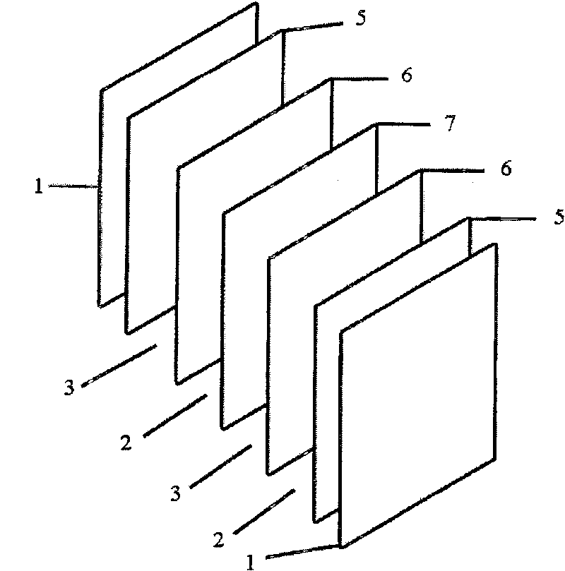
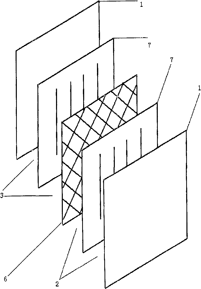
[0016] See attached figure 2 , the present invention---a liquid flow battery stack, including two end plates 1, a diaphragm 6, and two bipolar plates 7, the liquid flow battery stack is separated into positive electrodes by a diaphragm 6 between the two end plates 1 Two regions of electrolyte solution 2 and negative electrode electrolyte solution 3, a bipolar plate 7 with the same polarity as the electrolyte solution in the corresponding region and the same polarity on the front and back sides is arranged in each region, and the two poles of the same bipolar plate 7 in parallel.
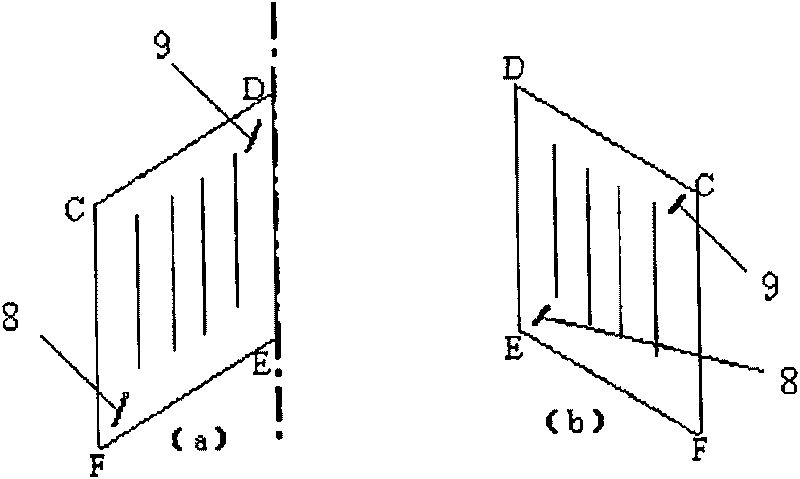
[0017] See attached Figure 4 (a), (b), in the present invention, the liquid inlet 8 of each bipolar plate 7 is all arranged at the same position below the bipolar plate 7, and the liquid outlet 9 is all arranged at the same position above the bipolar plate 7 .
PUM
 Abstract
Description
Claims
Application Information