Device and method for distributing water-inlet carbon source of sewage treatment plant

A technology for sewage treatment plant and water inflow, which is applied in the field of denitrification and phosphorus removal sewage treatment in sewage treatment plants, and can solve the problems of high cost, inability to distribute and utilize carbon sources, and adverse effects on the environment.

Active Publication Date: 2008-09-03
BEIJING DRAINAGE GRP CO LTD
View PDF0 Cites 16 Cited by
  • Summary
  • Abstract
  • Description
  • Claims
  • Application Information

AI Technical Summary

Problems solved by technology

[0002] Most of the current use of A 2 The nitrogen and phosphorus content of the urban sewage treatment plant effluent of the / O process cannot reach the standard at the same time. The main reason is that the limited carbon source in the influent sewage cannot be rationally allocated and utilized, resulting in vicious competition between denitrifying bacteria and phosphorus accumulating bacteria for the substrate. , cannot meet the needs of denitrification and phosphorus release at the same time
Usually, external carbon sources, such as methanol, acetic acid, etc., are used to improve the effect of biological denitrification, or chemical agents, such as ferrous sulfate, polyaluminum chloride, etc., are used to improve the effect of phosphorus removal, although this method has A certain effect, but the cost of this method is very high, and at the same time, the more use of chemical drugs will easily increase the re-pollution of sewage, which will have an adverse impact on the environment

Method used


Image

  • Device and method for distributing water-inlet carbon source of sewage treatment plant
  • Device and method for distributing water-inlet carbon source of sewage treatment plant
  • Device and method for distributing water-inlet carbon source of sewage treatment plant

Examples


Embodiment 1

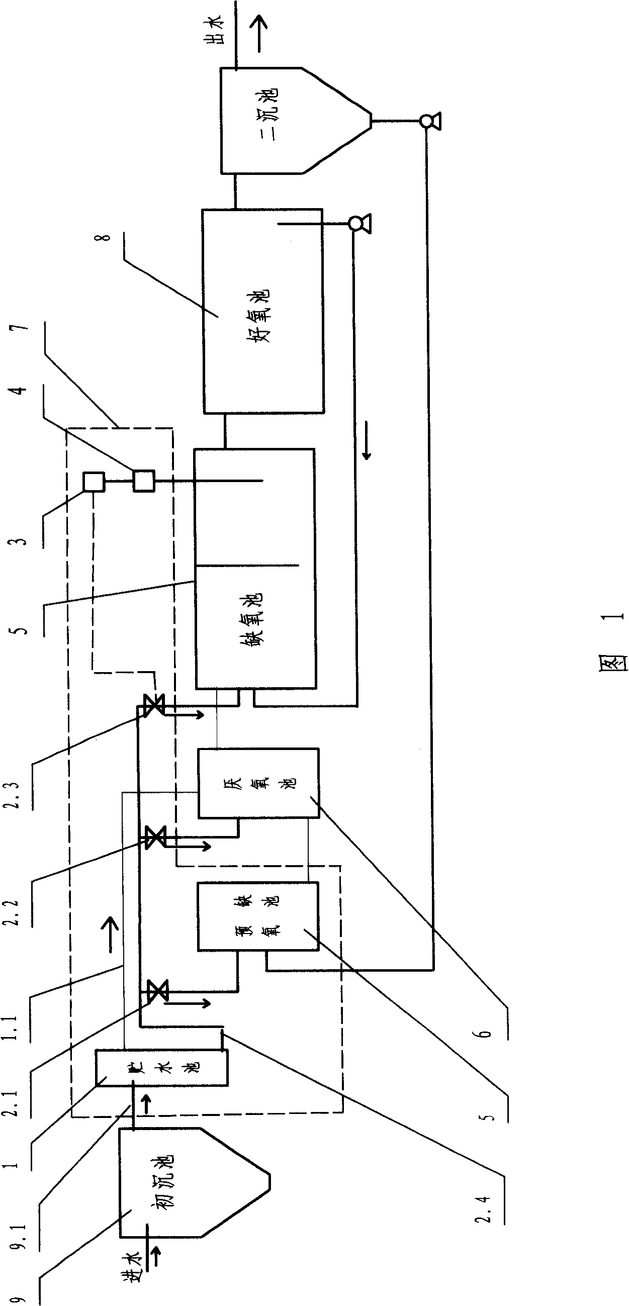
[0027] Below in conjunction with accompanying drawing and embodiment, the present invention is further described: Embodiment 1: a kind of device of sewage treatment plant distribution inlet carbon source, is provided with storage tank 1, pre-anoxic tank 5, valve A, B 2.1, 2.2 , an electric regulating valve 2.3, a controller 3, an online nitrate meter 4, the water storage tank is communicated with the outlet pipe 9.1 of the primary sedimentation tank 9, and is provided with an outlet pipe 2.4, through which the valve A 2.1 on the outlet pipe communicates with the pre-anoxic The pool is connected, through the valve B 2.2 and the electric regulating valve 2.3, it is connected with the anaerobic pool 6 and the anoxic pool 5 of the raw sewage treatment equipment respectively, and the anaerobic pool is connected with the overflow pipe 1.1 of the storage tank; the pre-anoxic pool is connected with the anaerobic pool The bottom of the oxygen tank is connected, the anaerobic tank is con...

Embodiment 2

[0029] 1), first in the traditional A 2 Before the / O process, a pre-anoxic section with a hydraulic retention time of 1 hour was set;

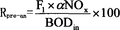
[0030] 2), according to the formula R pre - an = F 1 × α NO x BOD in × 100 (4-1) Calculate the water intake ratio required by the pre-anoxic pool as 15%, and manually adjust valve A so that the water intake ratio of the pre-anoxic pool reaches 15% of the total water intake;

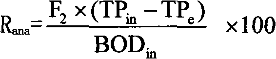
[0031] 3), according to the formula R ana = F 2 × ( TP in ...


PUM


Abstract

The invention discloses a device and a method for a sewage treatment plant to distribute an influent carbon source. The device is provide with a water storage tank, a pre-anoxic tank, a valve A and a valve B, an electric control valve, a controller and a on-line nitrate instrument, wherein the water storage tank is provided with a water outlet pipe, the on-line nitrate instrument is arranged in the aeration tank of the original sewage treatment equipment, the controller is connected with the on-line nitrate instrument through signal, and is controlled by and connected with the electric control valve. The device is matched with the original sewage treatment equipment; the method comprises setting the retention period of the water in the pre-anoxic tank, adjusting the water intake ratio between the pre-anoxic tank and the anaerobic tank, etc. The device and the method are applied to the matching application of the A<2>/O sewage treatment process, and the raw water carbon source is saved and reasonably used to ensure the sewage treatment effect to be better.

Description

technical field [0001] The invention belongs to a sewage treatment technology for denitrification and phosphorus removal in a sewage treatment plant, in particular to an auxiliary device and method for rationally distributing carbon sources in sewage to improve the effect of nitrogen and phosphorus removal in sewage treatment. Background technique [0002] Most of the current use of A 2 The nitrogen and phosphorus content of the urban sewage treatment plant effluent of the / O process cannot reach the standard at the same time. The main reason is that the limited carbon source in the influent sewage cannot be rationally allocated and utilized, resulting in vicious competition between denitrifying bacteria and phosphorus accumulating bacteria for the substrate. , cannot meet the needs of denitrification and phosphorus release at the same time. Usually, external carbon sources, such as methanol, acetic acid, etc., are used to improve the effect of biological denitrification, o...

Claims


Application Information

Patent Timeline
Patent Type & Authority Applications(China)
IPC IPC(8): C02F3/30
Inventor 王佳伟王洪臣甘一萍周军
Owner BEIJING DRAINAGE GRP CO LTD
Why Eureka
Try Eureka