Chemical water pump

A water pump and chemical technology, which is applied in the field of centrifugal chemical water pumps, can solve the problems of large input power, high energy consumption, and small output pressure (lift), and achieve the effect of large load, low energy consumption, and reduced energy consumption

Inactive Publication Date: 2008-09-03
杨军
View PDF0 Cites 4 Cited by
  • Summary
  • Abstract
  • Description
  • Claims
  • Application Information

AI Technical Summary

Problems solved by technology

[0004] It overcomes the problems of small output flow, small output pressure (head), poor stability, large input power, and high energy consumption of traditional centrifugal pumps, and provides a high-efficiency, stable and energy-saving centrifugal chemical water pump

Method used


Image

  • Chemical water pump
  • Chemical water pump
  • Chemical water pump

Examples


Embodiment Construction

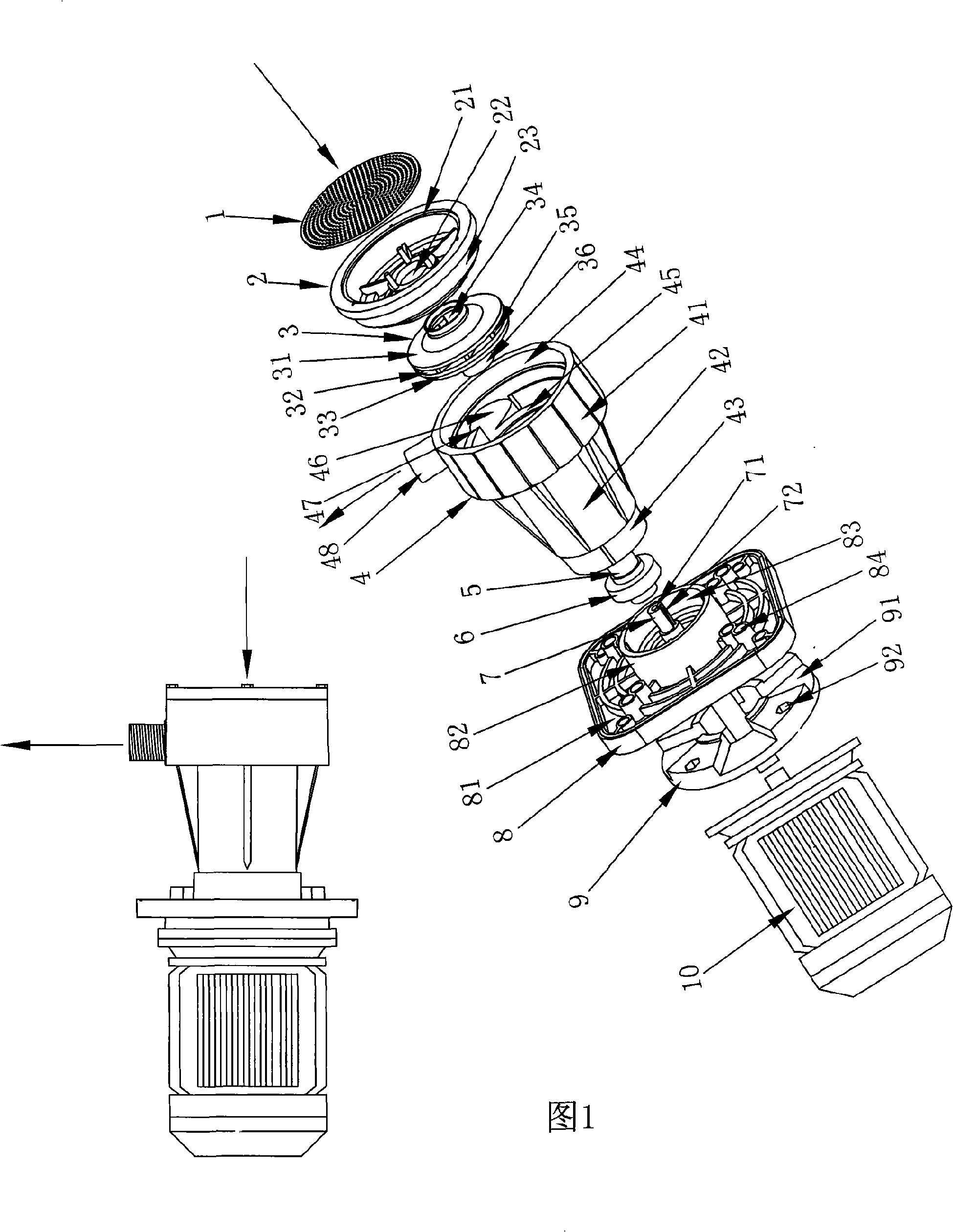
[0035] Please refer to Figure 1 to Figure 5 , a centrifugal chemical water pump comprising a filter screen 1, a pump cover 2, an impeller 3, a pump cavity 4, a motor shaft sleeve 5, a seal ring 6, a motor shaft 7, a pump base 8, a method Blue plate 9, a motor 10.

[0036] The pump base 8 includes a bottom plate 81 , a convex annular outer wall surface 82 on the bottom plate, a convex inverted conical inner wall surface 83 on the bottom plate, several screw holes 84 , and a first motor shaft hole 85 .

[0037] The pump base 8 also includes a flange 9, which includes a set of evenly distributed grooves 91 for ventilation and a set of screw holes 92 for connecting the motor.

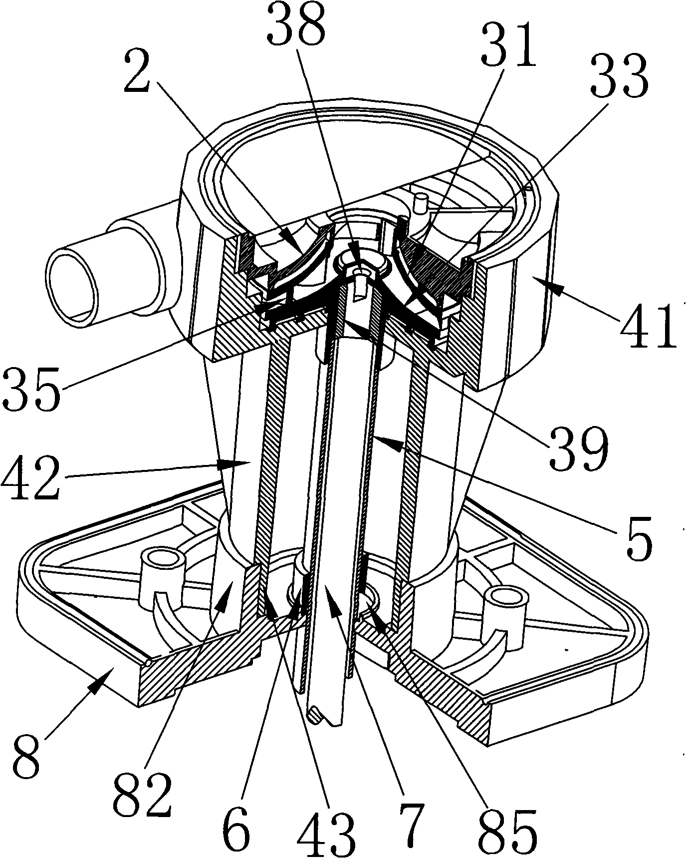
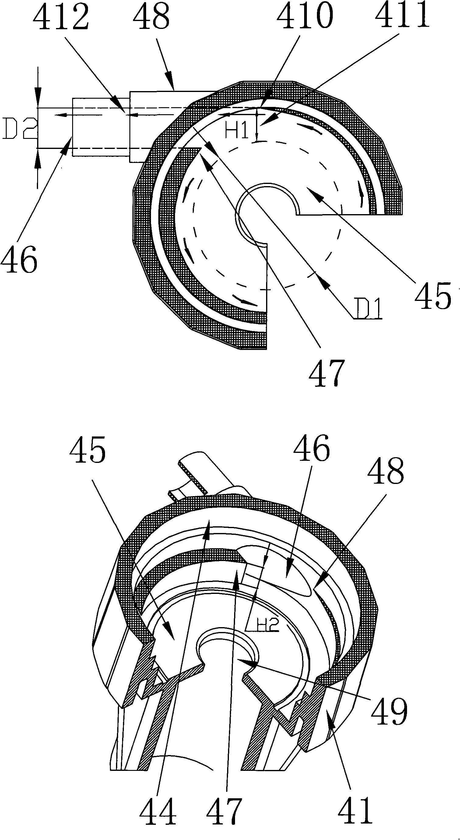
[0038] The pump chamber 4 includes an annular upper shell 41 , an annular lower shell 42 , and an outer conical wall 43 of the annular lower shell.

[0039] The annular upper shell 41 includes an annular inner wall 44 , a pump chamber upper shell bottom plate 45 , a water outlet 46 , a water outlet pipe ...


PUM


Abstract

The present invention provides a centrifugal chemical water pump comprising a pump body, an impeller, a motor driving the impeller. The pump body comprises a pump base, a pump cavity and a pump cover. The pump cavity is mounted on pump base, a ring protruding edge according to involute curve shape is arranged on side wall of pump cavity, the two ends of protruding edge are provided on two sides of water outlet, the side wall thickness of protruding edge changes gradually from thick to thin. The water outlet direction is identical to the tangent direction of most involute curve on side wall ofprotruding edge. The impeller in umbrella shape mounted in pump cavity comprises a lamina bracket wheel, an impeller cover, a water inlet, a water outlet. The impeller cover superposed on lamina bracket wheel, and the space forms impeller outlet, the height of water outlet can be adjusted by changing height of impeller. The pump cover is mounted on upper hull of pump cavity, the wall from inside of bottom of pump cover to inlet in center is inverse umbrella shape, and the surface combining dimension of pump cover and impeller are identical.

Description

technical field [0001] The invention relates to a centrifugal chemical water pump. The structural characteristics of the chemical water pump can enable the chemical water pump to input with low energy consumption and output with high practical efficiency under normal working conditions. Specifically, compared with traditional water pumps under the same output flow and output pressure (or lift) conditions, the required input motor power can be greatly reduced, and the effect of high energy saving and low energy consumption can be achieved. Background technique [0002] Centrifugal pumps are general-purpose mechanical equipment in industrial applications and are widely used in various fields of the national economy, especially in the electronics industry, chemical industry, and machining and manufacturing industries. Traditional centrifugal pumps have high input power and low output flow due to various factors such as defective structural design, unreasonable coordination of v...

Claims


Application Information

Patent Timeline
Patent Type & Authority Applications(China)
IPC IPC(8): F04D13/06F04D29/42F04D29/24
Inventor 杨军
Owner 杨军
Why Eureka
Try Eureka