
Quasi continuous green light laser with two-chamber interconnect V type structure one-way overlap output

A quasi-continuous, laser technology, applied in the laser field, can solve the problems of thermal lens effect, thermally induced birefringence, high photon number density, high power density, small spot area, and improved pumping efficiency.

Inactive Publication Date: 2008-09-03
NORTHWEST UNIV(CN)
View PDF0 Cites 6 Cited by
  • Summary
  • Abstract
  • Description
  • Claims
  • Application Information

AI Technical Summary

Problems solved by technology

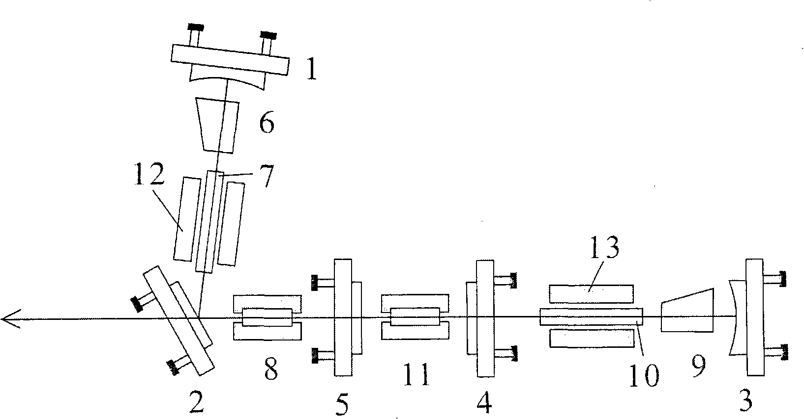
[0004] In order to overcome the shortcomings of too long cavity length, too high photon number density in the cavity, thermal lens effect and thermally induced birefringence when the double rods are connected in series, the technical solution of the present invention is solved in this way: a birefringence Cavity-interconnected V-shaped structure unidirectional overlapping output quasi-continuous green laser, including plano-concave total reflection mirror, its special feature is that two laser crystal rods are respectively placed in two parts of the optical path, and the optical components of part of the optical path are sequentially made of flat Concave mirrors, acousto-optic Q-switching crystals, laser crystals and high-power semiconductor pumping components on both sides of the laser crystals and flat folded green light output mirrors are connected with the adjustment frame to form a flat-concave V-shaped resonant cavity, and the other optical components of the optical path The frequency-doubling crystal, the full-reverse plane mirror, the frequency-doubling crystal, the second harmonic mirror, the laser crystal and the high-power semiconductor pump components on both sides of the laser crystal, the acousto-optic Q-switching crystal, and the whole The reverse plane mirror and the adjustment frame are connected to form a flat-concave straight cavity, and the flat-concave straight cavity and the flat-concave V-shaped resonant cavity are interconnected to form a V-shaped flat-concave straight cavity

Method used


Image

  • Quasi continuous green light laser with two-chamber interconnect V type structure one-way overlap output

Examples


Embodiment Construction

[0025] Accompanying drawing is embodiment of the present invention.

[0026] Below in conjunction with accompanying drawing, content of the present invention will be further described:

[0027] See attached figure 1 As shown, it includes plano-concave total reflection mirrors 1 and 3, and its two laser crystal rods are respectively placed in two parts of the optical path, and the optical components of a part of the optical path are sequentially composed of plano-concave total reflection mirror 1, acousto-optic Q-switching crystal 6, The laser crystal 7 and the high-power semiconductor pump components 12 on both sides of the laser crystal 7 and the plane folded green light output mirror 2 are connected with the adjustment frame to form a flat-concave V-shaped resonant cavity. The direction is followed by a frequency-doubling crystal 8, a full-reverse plane mirror 5, a frequency-doubling crystal 11, a second harmonic mirror 4, a laser crystal 10 and high-power semiconductor pum...


PUM


Abstract

The invention discloses a double-cavity interconnection V shape structure single-direction overlapping output quasi-cw green light laser which uses two semiconductor laser pumped components with same type pump two Nd:YAG crystals from side surface (semiconductor laser pumped Nd:YAG mode). Two modes are set in a plane concave V shape resonant cavity and a plane concave straight cavity, and form two beam 1064nm basic frequency lights with stabile operation, generate two beam frequency doubled lasers via acousto-optic Q switch and frequency doubled crystal, and reach plane folding mirror, single-direction overlapping output via plane folding mirror, and gain 532nm green light with average power as high as 206W. The laser has stable property, high frequency doubled efficiency, and is wide used in laser material processing, light storage, laser full-color display, laser medicine, scientific research, communication, national defence and amusement etc.

Description

technical field [0001] The invention belongs to the field of laser technology, and in particular relates to a 200W level semiconductor side-pumped double-cavity interconnected V-shaped structure unidirectional overlapping output quasi-continuous green laser. Background technique [0002] Since the birth of the world's first ruby ​​laser in the 1960s, with the continuous progress of various crystal materials and laser technology, the development of various lasers has also been extremely rapid, especially the development of high-power all-solid-state lasers is particularly eye-catching. , with its large output energy, high peak power, and higher than CO 2 Gas lasers are widely used in laser material processing, optical storage, laser full-color display, laser medicine, scientific research, communication, national defense, entertainment and other fields due to their short wavelength, reliable operation, and long service life. At present, multi-rod serial connection technology ...

Claims


Application Information

Patent Timeline
Patent Type & Authority Applications(China)
IPC IPC(8): H01S3/082H01S3/08H01S3/0941H01S3/16H01S3/042H01S3/117H01S3/127H01S3/109
Inventor 任兆玉白晋涛
Owner NORTHWEST UNIV(CN)
Learn More