

Simulation moving bed reactor and using method thereof
A technology for simulating moving beds and reactors, applied in chemical instruments and methods, chemical/physical processes, etc., can solve the problems of very demanding catalyst mechanical strength, catalyst particle wear, and large equipment, achieving low processing costs, avoiding mechanical Moving, simple structure effects
- Summary
- Abstract
- Description
- Claims
- Application Information
AI Technical Summary
Problems solved by technology
Method used
Image

Examples
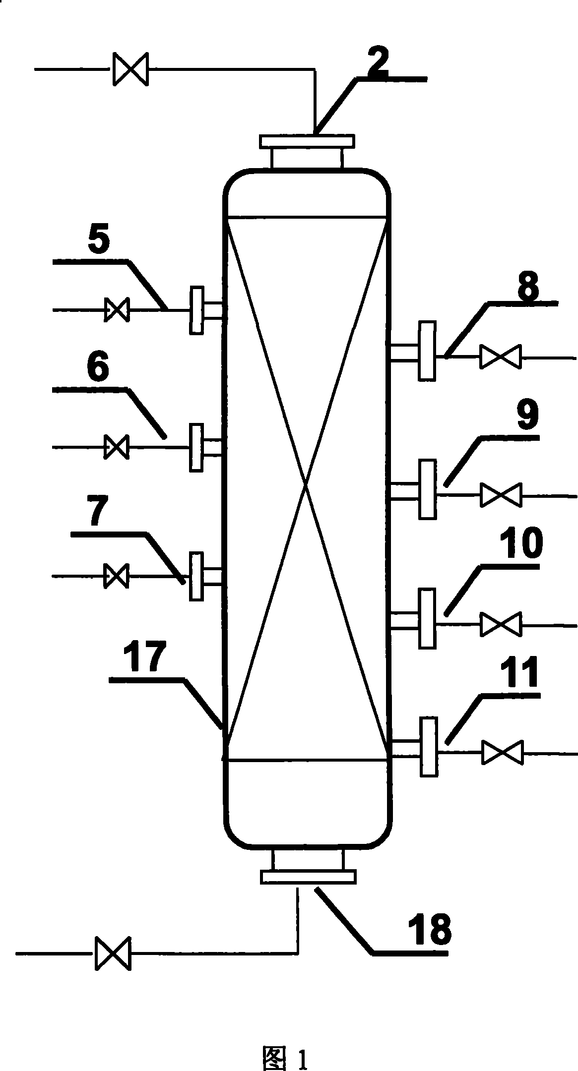
Embodiment 1
[0035] There are 5, 6, 7 raw material inlets and 8, 9, 10, 11 reaction product outlets on the side wall of the reactor shell 17, and the reaction product outlet ratio on the side wall of the reactor shell 17 is located on the side wall of the reactor shell 17 The import of raw materials is one more. The position of the first raw material inlet 5 on the side wall of the reactor shell 17 is higher than the position of the first reaction product outlet 8 on the side wall of the reactor shell 17, and the second on the side wall of the reactor shell 17 The position of the raw material inlet 6 is higher than the position of the second reaction product outlet 9 on the side wall of the reactor housing 17, and the position of the third raw material inlet 7 on the side wall of the reactor housing 17 is higher than that of the second reaction product outlet 9 located on the side wall of the reactor housing. The position of the third reaction product outlet 10 on the side wall of 17 has a...
Embodiment 2
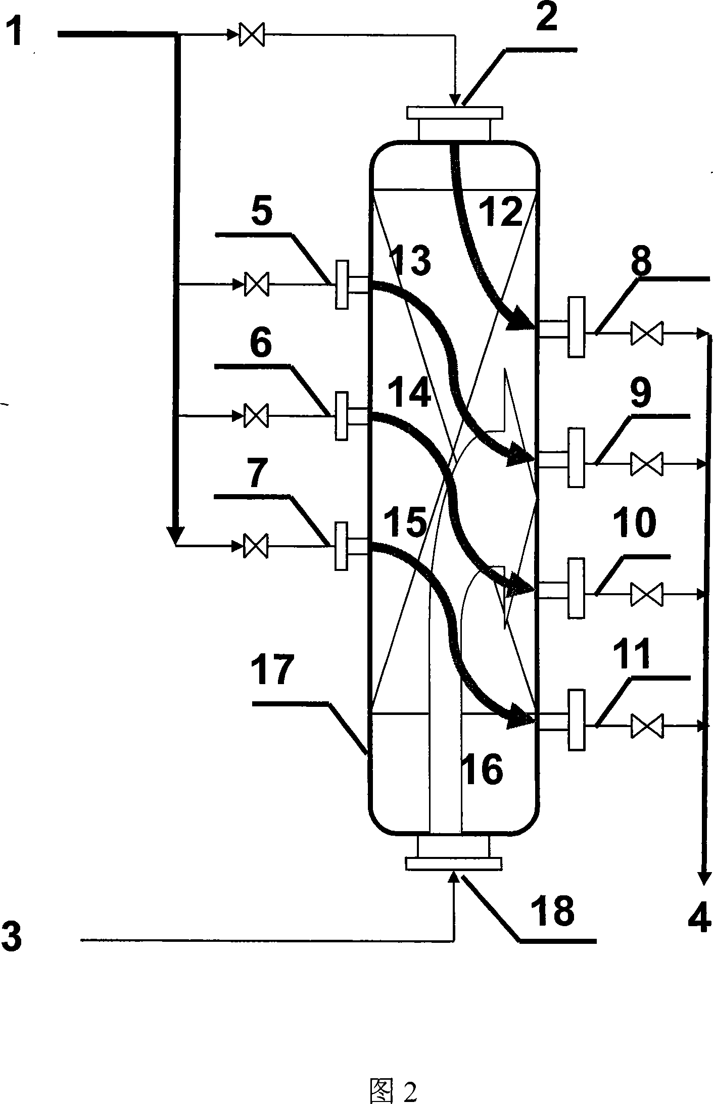
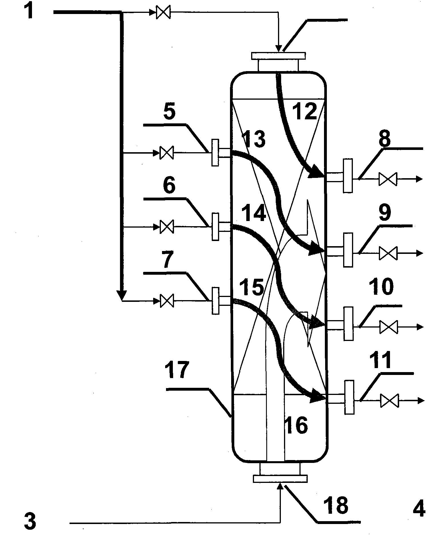
[0054] The valve of the material inlet 18 at the bottom of the reactor shell 17 is always in an open state, and other conditions and operation methods are exactly the same as those in Example 1.
[0055] Take part of the reaction product at a lower temperature after heat exchange and cooling as the low-temperature material, and enter the reactor shell 17 by making the material inlet 18 at the bottom of the reactor shell 17 flow in the direction opposite to the main reaction material flow direction, And leave the reactor from the same outlet as the main reaction product.
[0056] The reaction conditions and reaction results of the present embodiment are as follows:
[0057] Methanol weight space velocity: 1.0h -1
[0058] (relative to the catalyst between each pair of import and export)
[0059] Cycle ratio: 6
[0060] Reaction material inlet temperature: 380°C
[0061] Reaction material outlet temperature: 440°C
[0062] Reaction pressure: 0.5MPa
[0063] Material space...
PUM
 Abstract
Description
Claims
Application Information