Bending mode conversion type ultrasound wave torsional vibration energy converter

A mode conversion and torsional vibration technology, which is applied in the direction of material analysis using sound waves/ultrasonic waves/infrasonic waves, fluids that use vibrations, instruments, etc., can solve the problem of limiting the application range of ultrasonic torsional vibrations, small power and output amplitude of torsional transducers, and The manufacturing process is difficult to realize and other problems, and achieve the effect of simple structure, easy fabrication and bonding, and large vibration amplitude

Inactive Publication Date: 2008-09-10
BEIHANG UNIV
View PDF0 Cites 43 Cited by
  • Summary
  • Abstract
  • Description
  • Claims
  • Application Information

AI Technical Summary

Problems solved by technology

Theoretically, it is possible to make torsional transducers through tangentially polarized piezoelectric ceramics, but it is difficult to realize tangentially polarized piezoelectric ceramics in the manufacturing process.
Using piezoelectric ceramics polarized in the longitudinal direction can also achieve torsional vibration according to a certain bonding method, but the power and output amplitude of the torsional transducer manufactured by this method are small
The longitudinal ultrasonic vibration can also be converted into torsional vibration through a special structure, but the structure is more complicated
The above reasons limit the application range of ultrasonic torsional vibration

Method used


Image

  • Bending mode conversion type ultrasound wave torsional vibration energy converter
  • Bending mode conversion type ultrasound wave torsional vibration energy converter
  • Bending mode conversion type ultrasound wave torsional vibration energy converter

Examples


Embodiment Construction

[0032] The present invention will be further described in detail below in conjunction with the accompanying drawings.

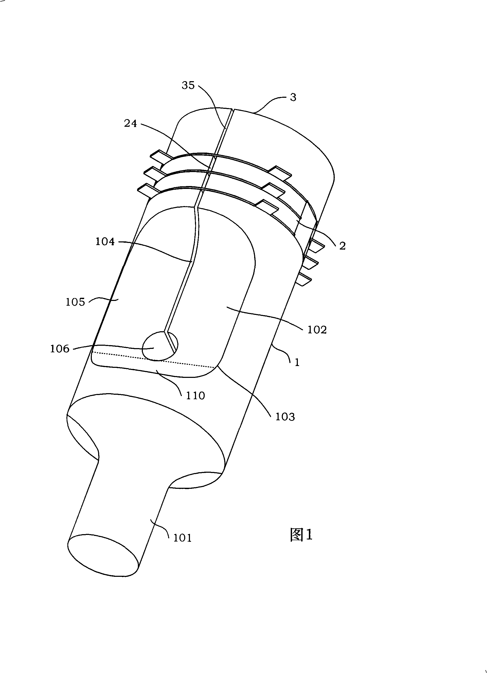
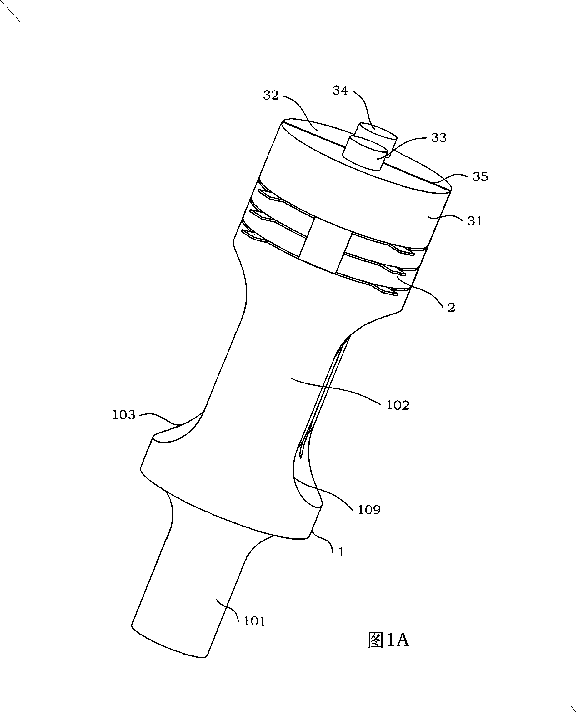
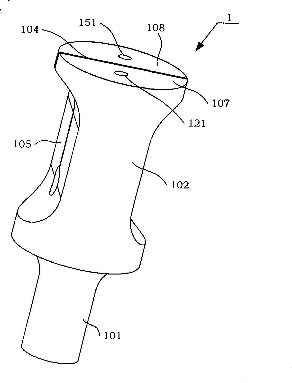
[0033] The present invention is a bending-torsion mode conversion ultrasonic torsional vibration transducer that can be used in multiple fields, which includes a bending-torsion vibrating body 1, a drive assembly 2, and a back cover 3 of the transducer.

[0034] Please refer to Figure 1, Figure 1A, figure 2 As shown, the drive assembly 2 is placed between the bending-torsion vibrating body 1 and the back cover 3 of the transducer, and passes through the through hole of the A end cover 31, the A through hole 22, and the A pre-tensioning screw 33 in sequence. Tighten the screw hole 121 to install the A end cover 31 and the insulating block 21 on the A top surface 107 of the bending-torsion vibrating body 1; pass the B pre-tightening screw 34 through the through hole of the B end cover 32 and the B through hole 23 in sequence , The B pre-tightening screw hole 151 i...


PUM

PropertyMeasurementUnit
radiusaaaaaaaaaa

Abstract

The invention discloses a bending-twisting conversion type ultrasonic torsion vibration transducer which comprises a bending-twisting vibrating body(1), a drive component (2) and a back cover (3) of the transducer; the drive component (2) is arranged between the bending-twisting vibrating body(1) and the back cover (3) of the transducer, and moreover, an A pretighting bolt (33) passes through the through hole of an A end cover (31), an A through hole (22) and an A pretighting screw hole (121) in turn through to arrange the A end cover (31) and an insulating block (21) on the A top surface (107) of the bending-twisting vibrating body(1); an B pretighting bolt (34) passes through the through hole of an B end cover (32), an B through hole (23) and an B pretighting screw hole (151) in turn to arrange the B end cover (32) and the insulating block (21) on the B top surface (108) of the bending-twisting vibrating body(1). A pair of bending vibrations with the same frequency swings and opposite vibrating directions generated by corresponding two groups of piezoelectric ceramics drive elements are amplified and transmitted to a converter by two bending arms; two bending vibrations are coupled and converted into a coupling torsion vibration (63) through a mode converter; a torsion vibration (64) is obtained and output after being amplified by an amplitude transformer (101), thus obtaining ultrasonic torsion vibration by a simpler mode.

Description

Technical field [0001] The invention relates to an ultrasonic torsional vibration transducer, which is suitable for ultrasonic vibration cutting (vibration drilling, vibration reaming and vibration tapping), ultrasonic welding, ultrasonic motor, ultrasonic fatigue experiment and other fields. Background technique [0002] In the field of vibration cutting, especially the processing of difficult-to-machine materials and the processing of small holes, torsional vibration has obvious advantages. Ultrasonic torsional vibration drilling can significantly reduce drilling force, improve drilling quality, and reduce exit burrs; ultrasonic torsional vibration reaming can suppress the built-up edge generated in low-speed machining and improve the surface quality of the hole; ultrasonic torsional vibration tapping can greatly Reduce tapping torque, improve tapping efficiency, improve tool life and thread quality. [0003] In the field of ultrasonic welding, the use of torsional vibration is...

Claims


Application Information

Patent Timeline
Patent Type & Authority Applications(China)
IPC IPC(8): B06B1/06B23B37/00B24B1/04B23K20/10H02N2/00G01N29/00
Inventor 张德远张文全李文
Owner BEIHANG UNIV
Why Eureka
Try Eureka