Oil spouting ignition apparatus

A fuel injector and igniter technology, which is applied to electric spark ignition controllers, engine ignition, spark plugs, etc., can solve the problems of high requirements for the processing of fuel injector mounting holes, difficult fuel injector installation and layout, and increased engine cost. Achieve the effect of favorable fuel atomization, compact structure, and reduced number of parts

Inactive Publication Date: 2008-09-10
CHERY AUTOMOBILE CO LTD
View PDF0 Cites 5 Cited by
  • Summary
  • Abstract
  • Description
  • Claims
  • Application Information

AI Technical Summary

Problems solved by technology

[0003] The fuel injector of a traditional engine is installed on the air intake of the engine. The fuel is generally sprayed from the fuel tank to the fuel rail, and directly sprayed into the air passage or cylinder through the fuel injector. The negative effect of fuel injection into the air passage is poor atomization. , it is easy to generate deposits on the inner wall of the air passage to form an oil film, which does not participate in the combustion of the engine, that is to say, the quality of the fuel actually injected by the injector is different from the quality of the fuel that actually participates in the combustion, but the information fed back by the oxygen sensor is only fuel The quality of the part involved in the combustion does not include the quality of the fuel deposited on the inner wall of the air passage, so the quality of the fuel fed back for combustion will have an error with the quality of the fuel sprayed by the injector, and the ECU will make a different feedback when it receives the biased information. There is a biased judgment in reality, therefore, there is always a small amount of fuel that is not completely burned, and is discharged into the atmosphere through exhaust gas, affecting engine emissions
In the traditional in-cylinder direct injection structure, the fuel injector is installed on the intake side of the cylinder head. Although the problem of engine emission is solved, the installation and arrangement of the fuel injector is difficult on the one hand. High requirements not only bring certain difficulties to the processing of parts, but also increase the cost of the engine

Method used


Image

  • Oil spouting ignition apparatus
  • Oil spouting ignition apparatus

Examples


Embodiment Construction

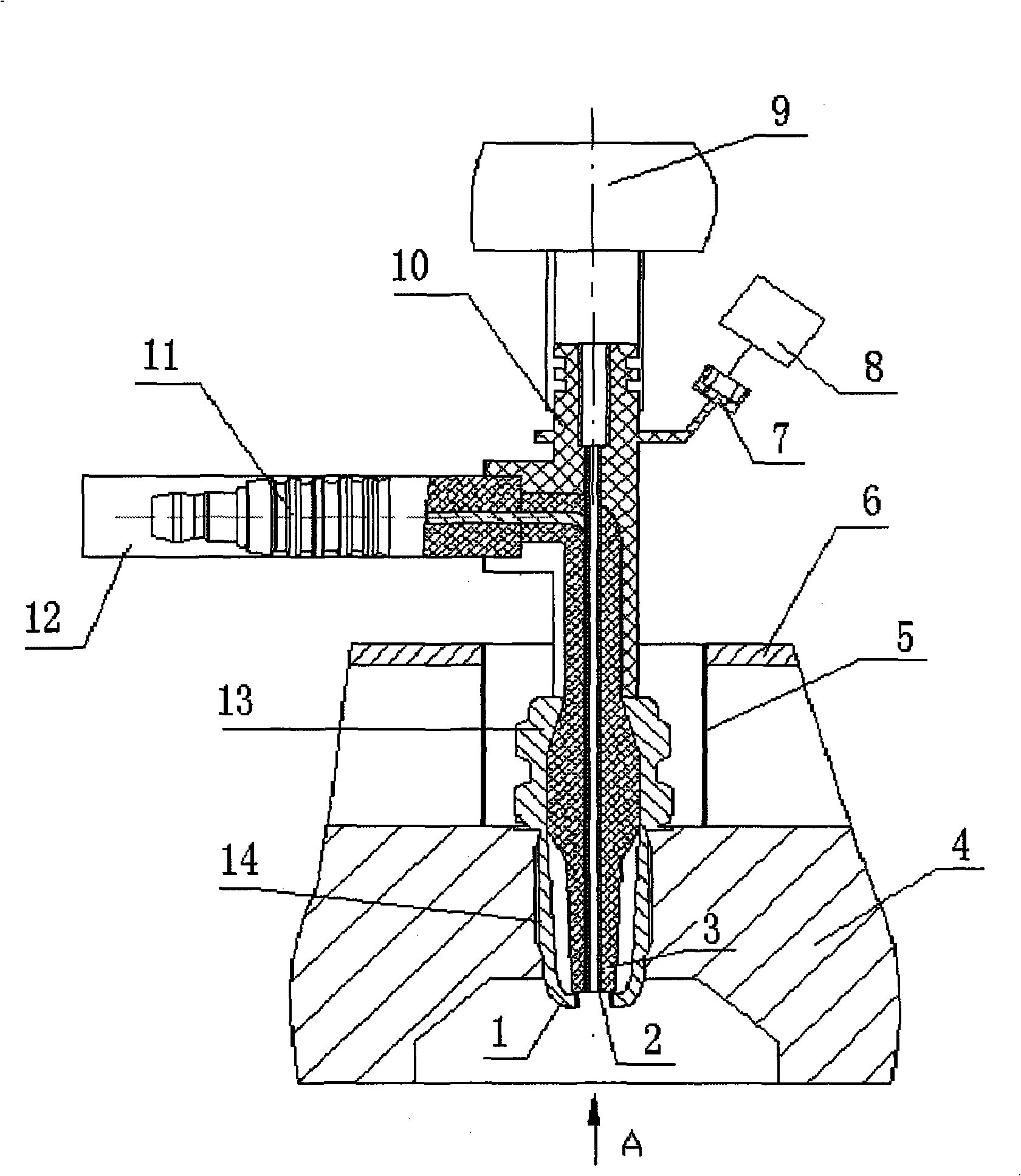
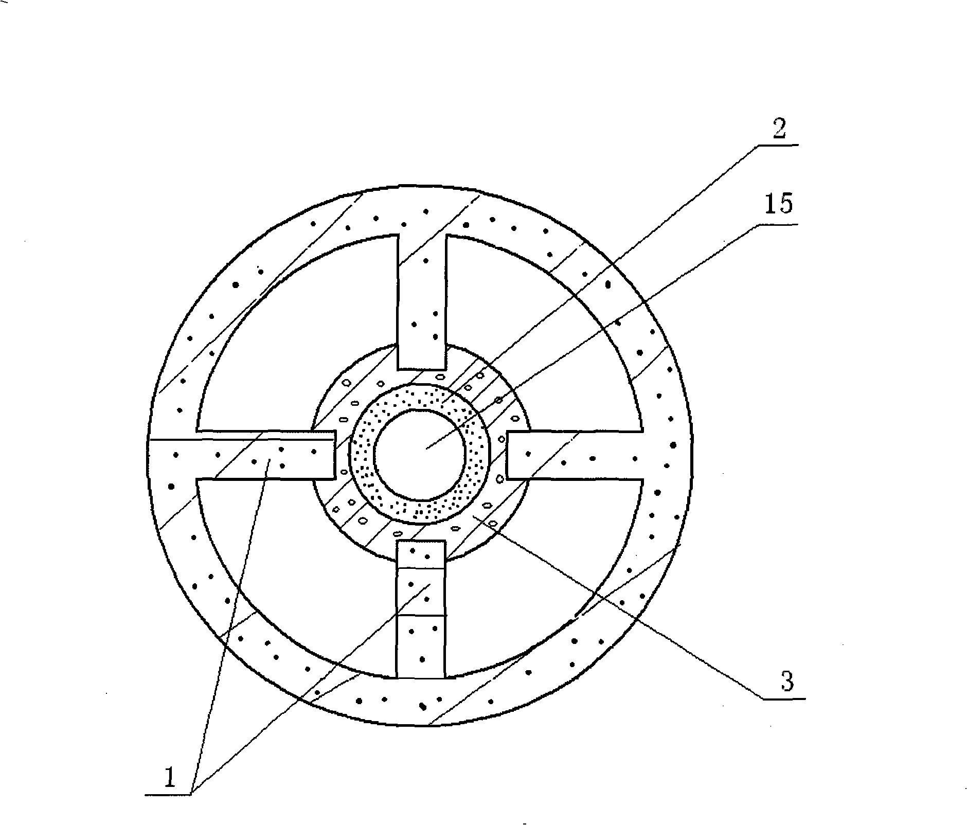
[0017] Such as figure 1 , figure 2 As shown, a fuel injection igniter includes a fuel rail 9, a cylinder head 4, an fuel injector 10, and a spark plug 11. The spark plug 11 includes a center electrode 2, an insulator 3, and four side electrodes 1. The insulator 3 wraps the center electrode 2 , The fuel injector 10 and the spark plug 11 are integrated, and the lower part of the fuel injector 10 overlaps with the lower part of the spark plug 11. The angle between the center line of the fuel injector 10 and the center line of the upper part of the spark plug 11 is 90 degrees, and the upper end of the fuel injector 10 In communication with the fuel rail 9, the lower end of the fuel injector 10 extends vertically into the center of the combustion chamber, and the middle of the fuel injector 10 has a copper core as the center electrode 2 of the spark plug 11, and the copper core is a piece with a fuel injection hole 15 A slender tube, the upper electrode of the spark plug 11 is in cont...


PUM


Abstract

The invention discloses an oil injection lighter, which comprises an oil rail (9), a cylinder cover (4), a fuel oil injector (10) and a spark plug (11), wherein, the spark plug (11) comprises a central electrode (2) and an insulator by which the central electrode (2) is coated; the fuel oil injector (10) and the spark plug (11) are integrated into a whole; the lower part of the fuel oil injector (10) is overlapped with the lower part of the spark plug (11); an included angle is formed between the upper part of the fuel oil injector (10) and the upper part of the spark plug (11); and the central electrode (2) on the lower part of the spark plug (11) is provided with a squirt hole (15) which is extended into a combustion chamber. The oil injection lighter adopts the structure that two independent important parts - the fuel oil injector and the spark plug of the prior engine are integrated into a part, thereby reducing the number of parts, being favorable for arrangement of an inlet pipe, the oil rail and the fuel oil injector, reducing the cost of the engine, and having a compact structure, good emission performance of the engine and low oil consumption of the engine.

Description

Technical field [0001] The invention relates to an engine, and in particular to a fuel injection igniter. Background technique [0002] Under normal circumstances, the spark plug of the engine is installed in the spark plug protection tube and screwed on the cylinder head through the thread on the spark plug. It is based on the gas discharge principle that the mixture is ionized under high pressure and becomes a conductor, and the high pulse generated by the ignition system of the gasoline engine is used. The voltage breaks down the 0.8-1.2mm gap between the center electrode and the side electrode of the spark plug. Once the area is broken down, the high-speed movement of ions and electrons form high-temperature and hot ionization channels, and sparks are generated, which then ignite the combustion chamber of the gasoline engine. The combustible mixed gas, the gas expands in a short time to generate power, which makes the engine run and output energy. At present, most engine spar...

Claims


Application Information

Patent Timeline
Patent Type & Authority Applications(China)
IPC IPC(8): F02M57/06
Inventor 冯武堂汪久高杨厚忠张作民杨谊林
Owner CHERY AUTOMOBILE CO LTD
Why Eureka
Try Eureka