Oil-free fluid machine having two or more rotors

A fluid machinery, rotor housing technology, applied in the direction of rotary piston machinery, mechanical equipment, liquid fuel engines, etc., can solve the problems of plastic gear damage, reduce working life and other problems, achieve balanced torque transmission, prolong working life, easy to use. replacement effect

Inactive Publication Date: 2008-09-10
ANEST IWATA CORP
View PDF0 Cites 6 Cited by
  • Summary
  • Abstract
  • Description
  • Claims
  • Application Information

AI Technical Summary

Problems solved by technology

So, when the increased driving torque is transmitted from the driving motor to one rotor, all the driving torque is transmitted to the other rotor via the synchronous gear, and the plastic gear may be damaged or reduce the working life due to the increased torque

Method used


Image

  • Oil-free fluid machine having two or more rotors
  • Oil-free fluid machine having two or more rotors
  • Oil-free fluid machine having two or more rotors

Examples


Embodiment Construction

[0015] A preferred embodiment of the present invention will be described with reference to the drawings. However, it should be pointed out that unless otherwise specified, dimensions, materials, relative positions, and components in the embodiments should be interpreted as illustrative only, and not as limiting the protection scope of the present invention.

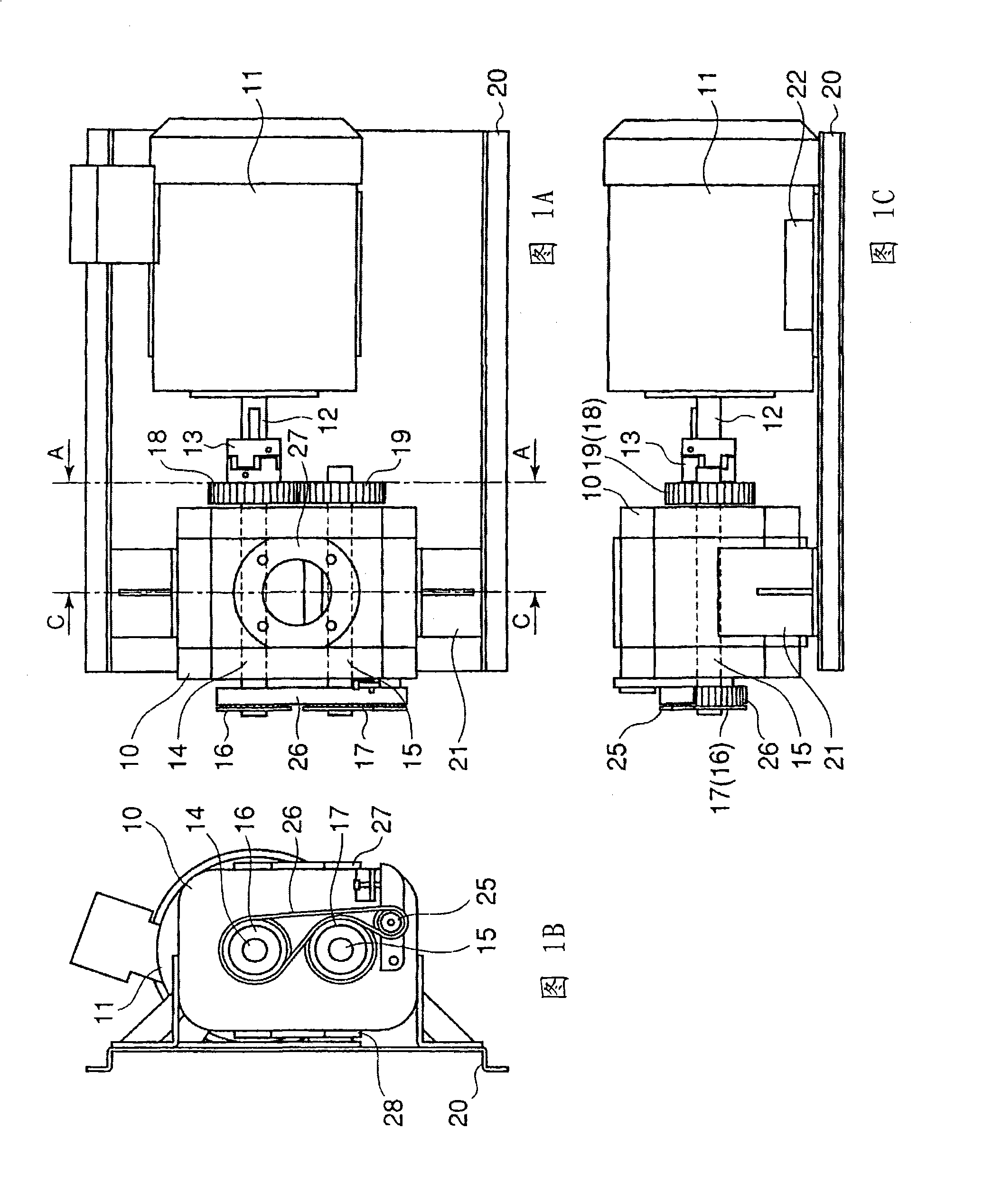
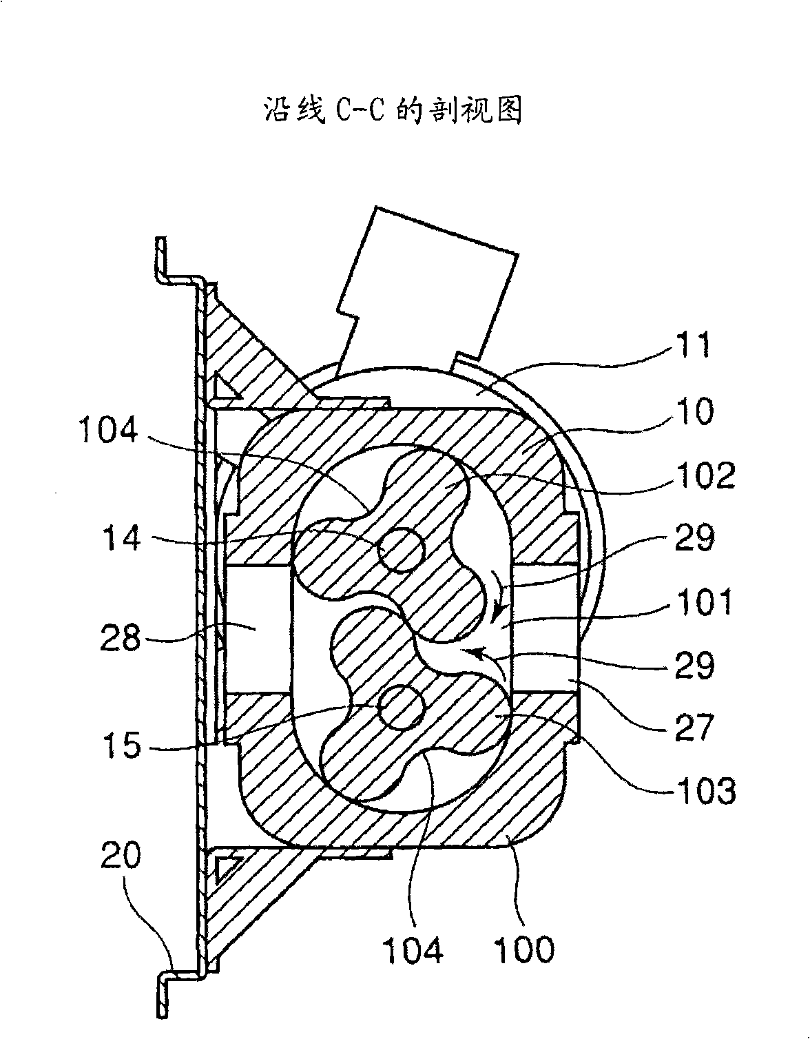
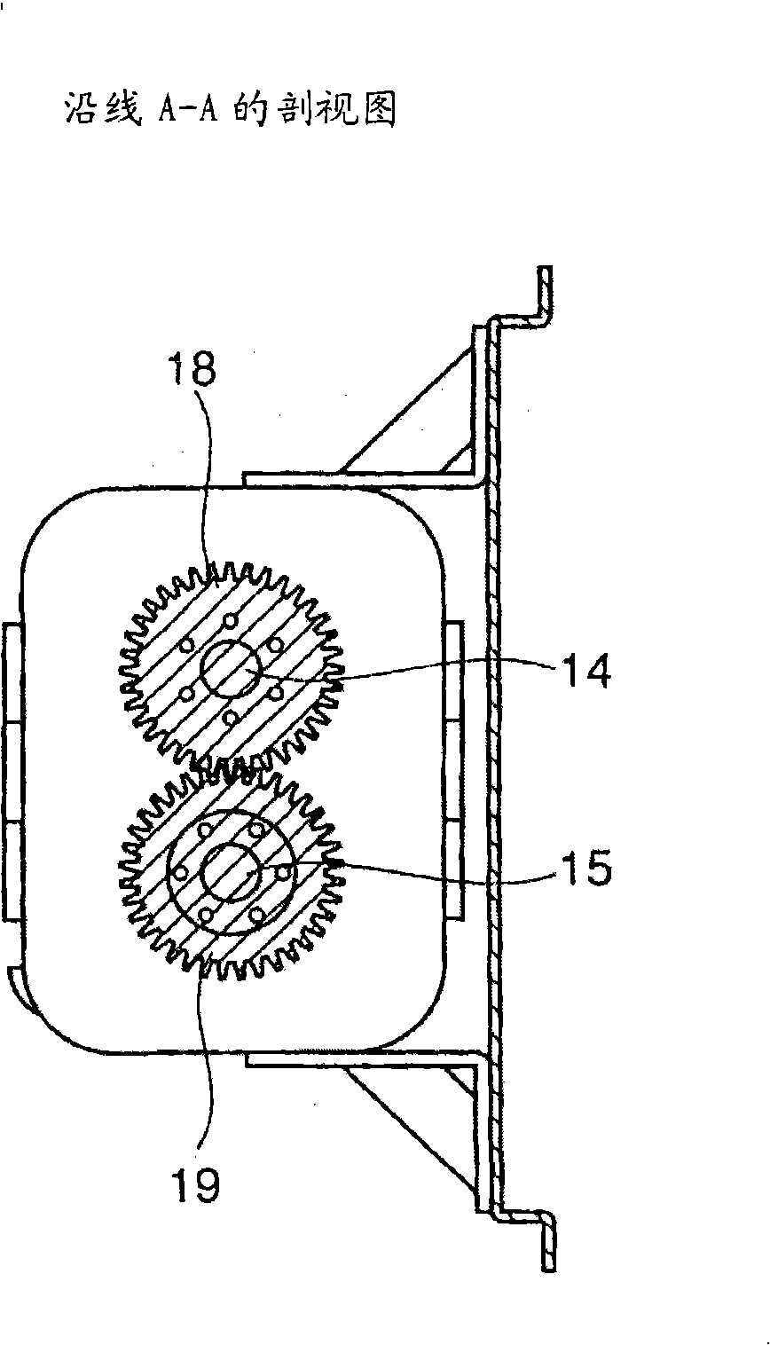
[0016] 1A is a plan view of an oil-free fluid machine constituted as a dry Roots mechanical vacuum pump with a drive transmission mechanism according to the present invention, FIG. 1B is its side view, and FIG. 1C is its front view. Figure 2A is a cross-sectional view along line A-A in FIG. 1A, and Figure 2B It is a transverse cross-sectional view along line C-C in FIG. 1A. Although the present invention will be described taking a dry mechanical vacuum Roots pump as an example, and it has two rotors equipped with a drive transmission mechanism, the drive transmission mechanism applied to the fluid machine of the present...


PUM


Abstract

An oil-free fluid machine unit is provided of which the fluid machine has two or more rotors and torque transmission between the rotors can be performed without a need of using lubrication oil thereby eliminating contamination induced by lubrication oil and without reduction of longevity of the synchronizing gears. The drive shaft 12 of the drive motor 11 is connected to the rotor shaft 14 of the fluid machine, synchronization gears 18 and 19 are attached to the rotor shafts 14 and 15 at the motor 11 side end of the rotor shafts respectively, and pulleys 16 and 17 are attached to the rotor shafts 14 and 15 at the other side ends respectively opposite to the motor 11 and a belt is looped over the pulleys so that the pulleys are rotated in counter direction to each other. At least one of the synchronization gears is made of plastic material. Thus, torque transmission between the rotors is done in two ways, via synchronization gear drive and belt drive.

Description

technical field [0001] The present invention relates to an oil-free fluid machine with two or more rotors, in particular to a dry sealed mechanical vacuum pump such as Roots type, screw type and claw type vacuum pumps , which has two or more rotors that rotate synchronously with each other to achieve balanced torque transmission without the need for lubricating oil for lubricating the rotor drive mechanism, thereby eliminating oil contamination. Background technique [0002] The fluid machine has two or more counter-rotating meshing vane rotors accommodated in a rotor housing, and the air trapped in the gap between the rotor housing wall and the rotor surface is removed by the rotors rotating synchronously with each other, which This kind of fluid machinery is widely used as a vacuum pump, such as Roots vacuum pump, claw vacuum pump and screw vacuum pump. [0003] In these dry mechanical vacuum pumps with two or more vane rotors, synchronous gears made of metal are usually ...

Claims


Application Information

Patent Timeline
Patent Type & Authority Applications(China)
IPC IPC(8): F04C25/02F04C18/12F04C29/00
CPCF04C18/126F04C29/005
Inventor 谷川志郎
Owner ANEST IWATA CORP
Why Eureka
Try Eureka