
Supporting structure for supporting separation bearing

A release bearing and supporting structure technology, applied in clutches, mechanical drive clutches, mechanical equipment, etc., can solve the problems of increasing clutch operating force, increasing wear of the separating hub, worsening operating feeling, etc., to improve operating feeling, reduce production costs, The effect of reducing the operating force

Inactive Publication Date: 2008-09-10
DAIHATSU MOTOR CO LTD
View PDF3 Cites 0 Cited by
  • Summary
  • Abstract
  • Description
  • Claims
  • Application Information

AI Technical Summary

Problems solved by technology

[0007] According to this structure of Patent Document 2, although it is not necessary to provide a bearing support on the front cover, since the release hub is arranged on the inner diameter side of the release bearing, the radial dimension cannot be greatly reduced.
Moreover, since the release hub slides on the rotating driven shaft, the wear of the release hub is further increased compared with the case where the release hub slides on the bearing support, and due to the frictional resistance between the driven shaft and the release hub increased clutch operating force
And worsened the operating feeling

Method used


Image

  • Supporting structure for supporting separation bearing
  • Supporting structure for supporting separation bearing
  • Supporting structure for supporting separation bearing

Examples


Embodiment Construction

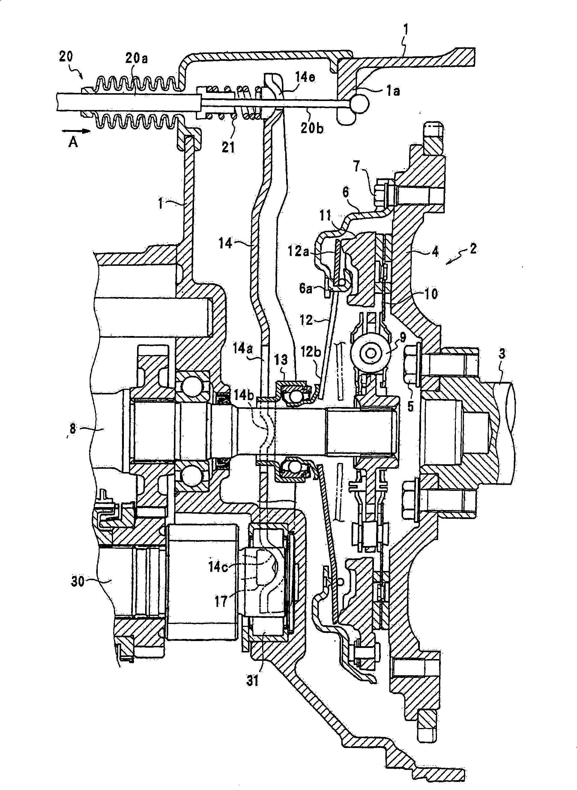
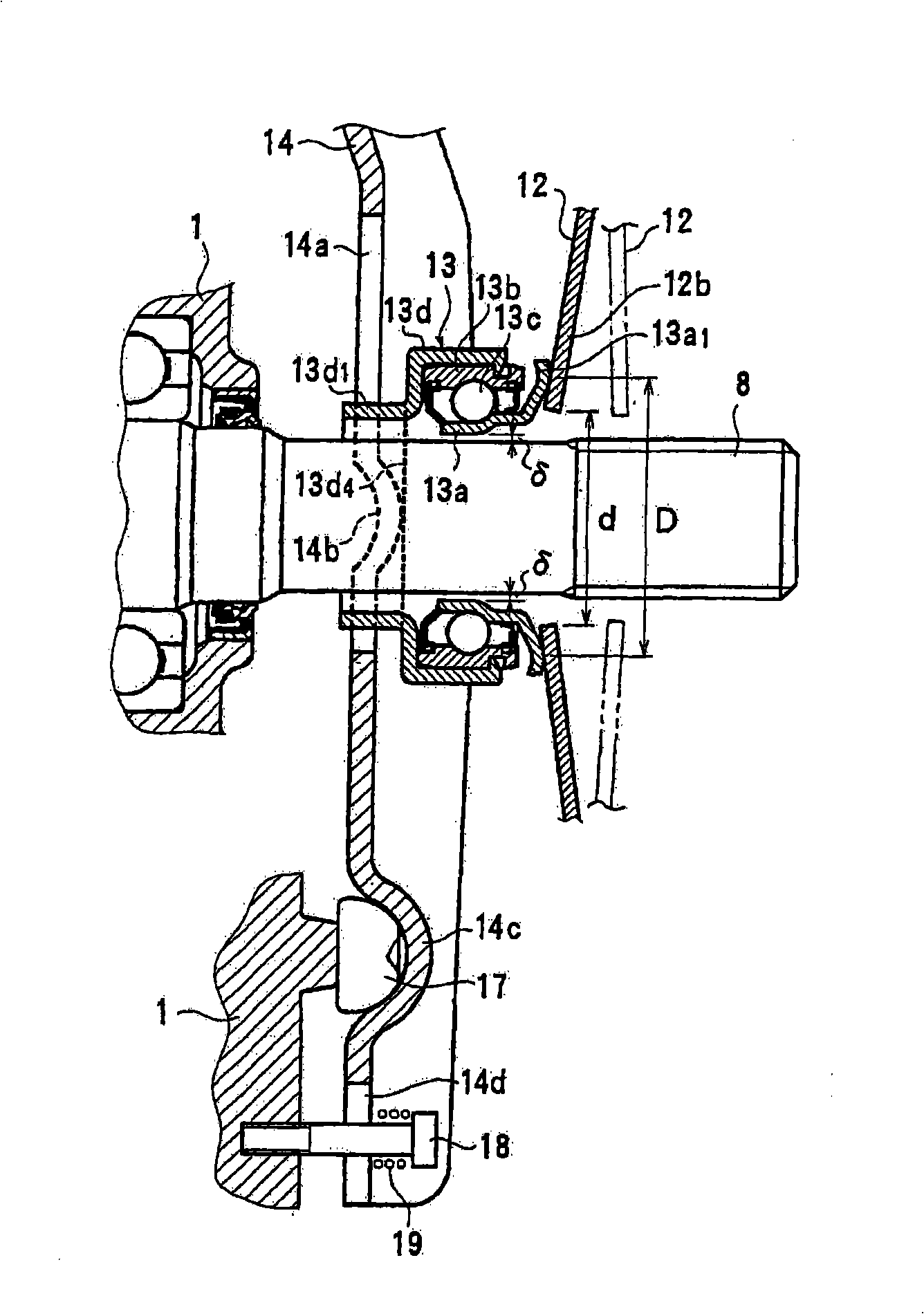
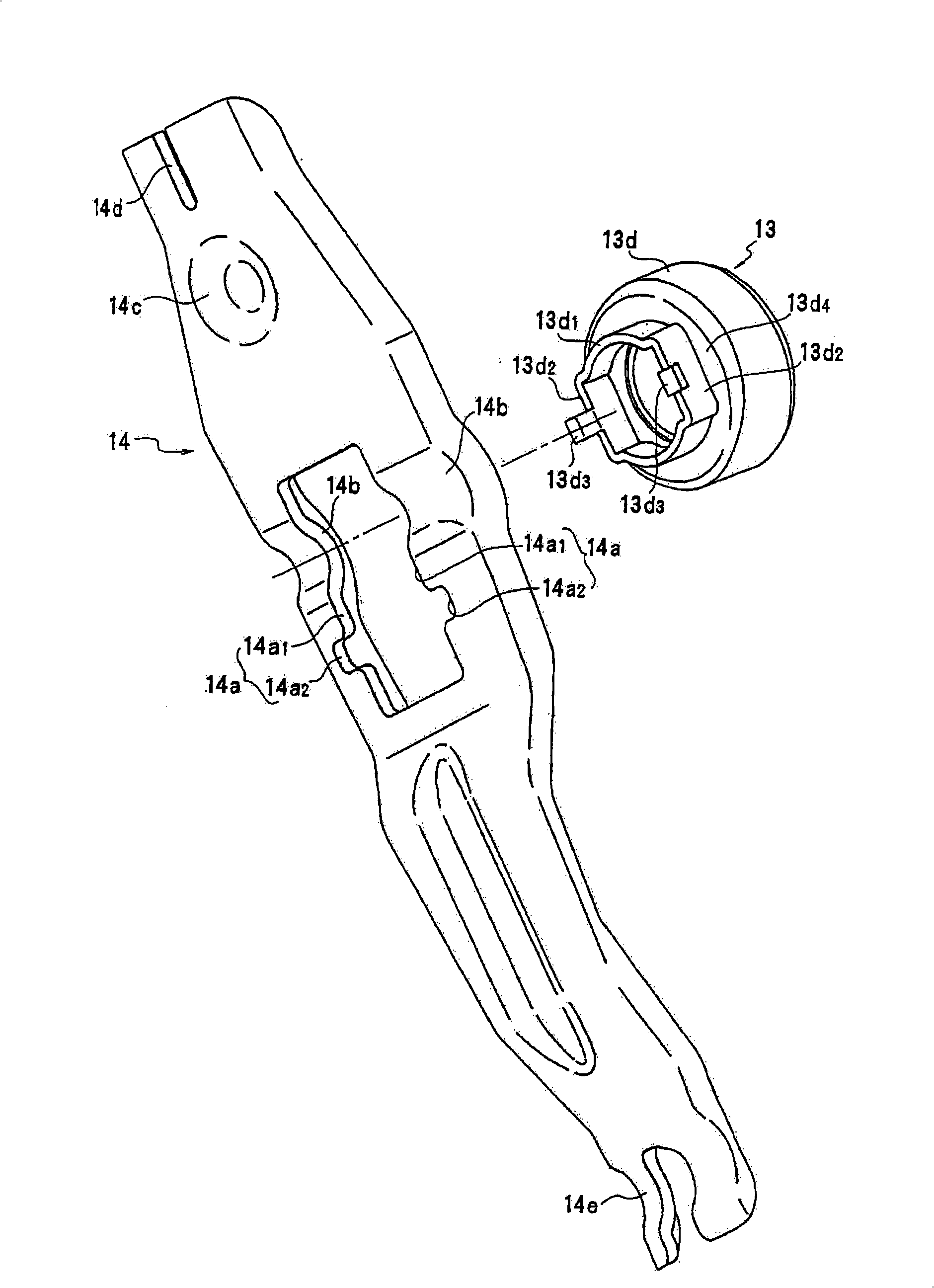
[0020] figure 1 A clutch device for an automotive manual transmission is shown as one of the exemplary embodiments of the present invention. A dry single-plate clutch 2 is accommodated in a front cover 1 which is a part of the transmission housing. The clutch 2 includes a flywheel 4, a clutch cover 6, a clutch disc 10, a pressure plate 11, a diaphragm spring 12, a release bearing 13, a release fork 14, and the like.

[0021] The flywheel 4 is fastened to the rear end 3 of the engine output shaft (drive shaft) by bolts 5 , and the clutch cover 6 is fastened to the rear surface of the flywheel 4 by bolts 7 . The input shaft (driven shaft) 8 of the manual transmission is arranged coaxially with the engine output shaft 3 . Its front end portion is inserted into the axially central portion of the clutch cover 6 . The clutch disc 10 is attached to the input shaft 8 so as to be rotatable together with the input shaft 8 via the torsion damper 9 . The pressure plate 11 and the diap...


PUM


Abstract

The invention provides a support structure for supporting a separate bearing in a clutch device that processes or interrupts power transmission from a driving shaft to a driven shaft. The support structure includes: a diaphragm spring that is provided with an inner circumference part, the inner part is formed with a symmetric shape relative to an axis center of the driven shaft, the diaphragm is combined with the driving shaft; the separate bearing that is provided with an inner ring through an outside circumference of the driven shaft with a given radial clearance, the separate bearing is provided with an outside ring and an annular butt jointing part of one end of the inner ring with a method for line contacting to the inner circumference part of the diaphragm spring; and a separate fork that can push the outside ring of the separate bearing; wherein, the separate bearing is shift along axial direction of the driven shaft through vibrating the separate fork by the clutch device, consequently the diaphragm spring is converted for processing or interrupting power transmission from the driving shaft to the driven shaft.

Description

[0001] Cross References to Related Applications [0002] This application claims priority from Japanese Patent Application No. 2007-058128 filed on March 8, 2007, the entire contents of which are hereby incorporated by reference. technical field [0003] The present invention relates to a support structure for supporting a release bearing in a clutch device, and more particularly, to a support structure for supporting a release bearing for urging a diaphragm spring for a release clutch. Background technique [0004] Conventionally, as shown in Patent Document 1, a dry type single-plate clutch for a manual transmission is known. In this known dry single-plate clutch, the aligned release bearing is supported on a cylindrical bearing carrier integrally formed on the front cover, which is part of the transmission housing. That is, a spring is interposed between the outer ring of the release bearing and the cover, and a release hub made of synthetic resin is slidably arranged on...

Claims


Application Information

Patent Timeline
IPC IPC(8): F16D23/14
Inventor 中尾章裕嵜迫邦彦北村健
Owner DAIHATSU MOTOR CO LTD
Learn More