Material nanometer dynamic performance test two freedom degree loading unit

A loading device and degree-of-freedom technology, which is used in measuring devices, analyzing materials, and testing the strength of materials by applying stable tension/pressure. problem, to achieve the effect of low cost, improved driving accuracy and high efficiency

Inactive Publication Date: 2008-09-10
JILIN UNIV
View PDF0 Cites 11 Cited by
  • Summary
  • Abstract
  • Description
  • Claims
  • Application Information

AI Technical Summary

Problems solved by technology

[0003] The object of the present invention is to provide a kind of material in order to solve the problems that the micro-loading device in the existing in-situ (In Situ) mechanical property testing system cannot detect the loading force or the detection accuracy is not high, the structure of the detection system is complicated, and the cost is expensive. Two-degree-of-freedom loading device in nanomechanical performance testing

Method used


Image

  • Material nanometer dynamic performance test two freedom degree loading unit
  • Material nanometer dynamic performance test two freedom degree loading unit
  • Material nanometer dynamic performance test two freedom degree loading unit

Examples


Embodiment Construction

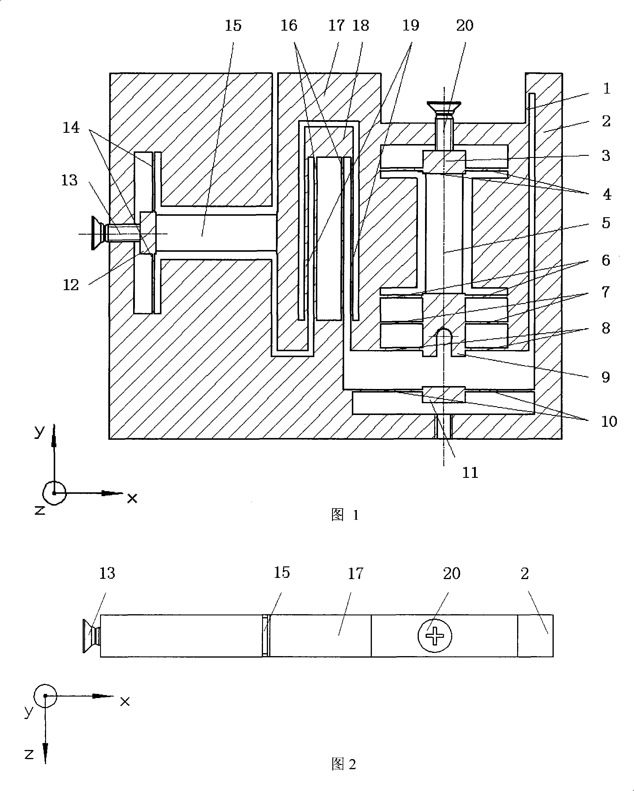
[0018] Referring to Figures 1 and 2, the indenter 9 is connected to the x-axis movement mechanism 17 by a plurality of thin-walled flexible hinges 6, 7, 8; the said x-axis positive movement mechanism 17 has a plurality of thin-walled flexible hinges 16, 19 is connected to the rigid base 2; said driving element is composed of a piezoelectric stack, wherein the piezoelectric stack 5 is integrally installed between the x-axis pretension mechanism 12, 13, 14 and the x-axis movement mechanism 17 Between, wherein the piezoelectric stack 15 is integrally installed between the indenter 9 and the indenter pretension mechanism 3, 4, 20; said x-axis pretension mechanism 12, 13, 14 consists of a rigid body 12, a screw 13 and flexible hinge 14;

[0019] The specific working process is as follows:

[0020] In the initial state, the piezoelectric stacks are not charged, and the system is in a free state. By adjusting the pretension mechanism, the position of the indenter 9 in the x and y di...


PUM


Abstract

The invention relates to a device used for testing material nanometer scale performance, particularly to a micro-loading device used for testing material nanometer scale mechanical performance. The device consists essentially of a base, an x axial direction motion mechanism, a pressure head, a driving component and a preloading mechanism, wherein, the pressure head is connected to the x axial direction motion mechanism by a plurality of flexible hinges which have thin walls; the x axial direction motion mechanism is connected to a rigid base by a plurality of flexible hinges which have thin walls; the driving component consists of piezoelectric stacks, one of the piezoelectric stack is wholly arranged between an x axial direction preloading mechanism and the x axial direction motion mechanism while the other piezoelectric stack is wholly arranged between the pressure head and the pressure head preloading mechanism, a rigid body used for holding the tested material is arranged at the lower part of the pressure head, and the rigid body is connected to the rigid base by the flexible hinge that is connected with the rigid body. In order to solve the problems that the loading force can not be tested by the prior art, or the testing accuracy is not high, the system structure is complicated and the cost is high, etc., the device of the invention has the advantages of simple and compact structure and low cost, etc.

Description

technical field [0001] The invention relates to the fields of material mechanical performance testing, ultra-precision processing equipment, micro-electro-mechanical systems, precision optical element processing, ultra-precision machining equipment, automobile manufacturing, aerospace nanoscience and biomedical engineering, and particularly relates to the mechanical properties of nanoscale materials And precision loading devices in mechanical behavior tests, especially involving in-situ (In Situ) loading devices in nanoscale material mechanical performance tests using scanning electron microscopes or transmission electron microscopes and other equipment. technical background [0002] In recent years, with the rapid development of microelectronics, biomedicine, semiconductors, optics, data storage, ultra-precision machinery and its manufacturing, people have put forward more and more research on the evaluation, testing methods and mechanical behavior of materials nanomechanica...

Claims


Application Information

Patent Timeline
Patent Type & Authority Applications(China)
IPC IPC(8): G01N3/08G01N13/10G01B21/32H01J37/26G01N23/02G01N23/22
Inventor 赵宏伟
Owner JILIN UNIV
Why Eureka
Try Eureka