

Source pole driver
A source driver, transceiver technology, applied in the direction of instruments, static indicators, etc., to achieve the effect of reducing the number of wires
- Summary
- Abstract
- Description
- Claims
- Application Information
AI Technical Summary
Problems solved by technology
Method used
Image

Examples
Embodiment Construction
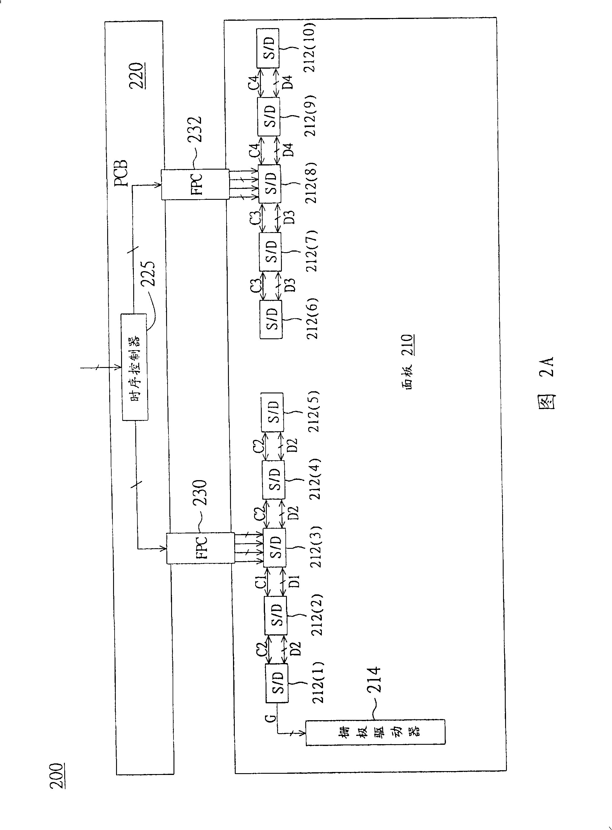
[0052]Please refer to FIG. 2A , which shows a schematic diagram of a liquid crystal display using a Chip On Glass (COG) package according to a preferred embodiment of the present invention. The liquid crystal display 200 includes: a panel 210, a plurality of source drivers (Source Driver, S / D) 212(1)-211(10), at least one gate driver (Gate Driver) 214, a printed circuit board 220 and a flexible circuit board 230 and 232. The source driver 212 and the gate driver 214 are disposed on the glass substrate of the panel 210 . The timing controller 225 is arranged on the printed circuit board 220 to receive image data and control signals, and then transmit them to the source drivers 212(3) and 212(8) through flexible circuit boards (FPC) 230 and 232 after processing. The source drivers 212(3) and 212(8) respectively transmit the received image data and source control signals to the adjacent source drivers 212(1), 212(2), 212(4) through the wires on the glass substrate. ), 212(5) an...
PUM
 Abstract
Description
Claims
Application Information