Chirp pulse regeneration amplification method for pump light enhanced light parameter

A chirped pulse, regenerative amplification technology, applied to lasers, laser components, electrical components, etc., can solve the problems of signal light saturation effect, pump light cannot be used efficiently, etc., and achieve the effect of improving conversion efficiency

Inactive Publication Date: 2008-09-10
EAST CHINA NORMAL UNIV
View PDF0 Cites 4 Cited by
  • Summary
  • Abstract
  • Description
  • Claims
  • Application Information

AI Technical Summary

Problems solved by technology

[0004] The purpose of the present invention is to provide a pump light enhanced optical parametric chirped pulse regeneration amplification method for the shortcomings of the above-mentioned prior art. The method utilizes the special structure of the ring cavity to superimpose the first pump light in the cavity. Enhancement, and use the optical path difference between the signal light and the pump light in their respective cavit

Method used


Image

  • Chirp pulse regeneration amplification method for pump light enhanced light parameter
  • Chirp pulse regeneration amplification method for pump light enhanced light parameter
  • Chirp pulse regeneration amplification method for pump light enhanced light parameter

Examples


Embodiment Construction

[0016] The features of the present invention and other related features will be further described in detail below in conjunction with the accompanying drawings through embodiments, so as to facilitate the understanding of those skilled in the art:

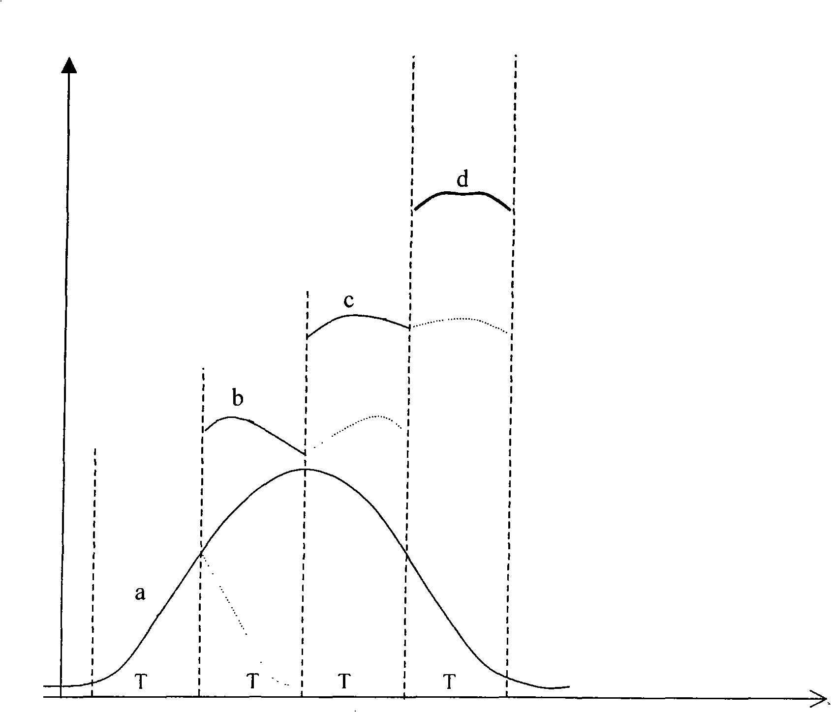
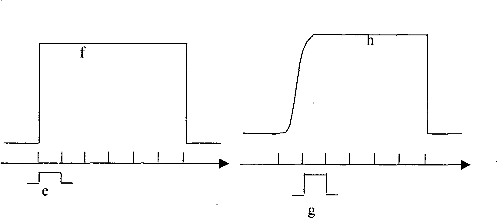
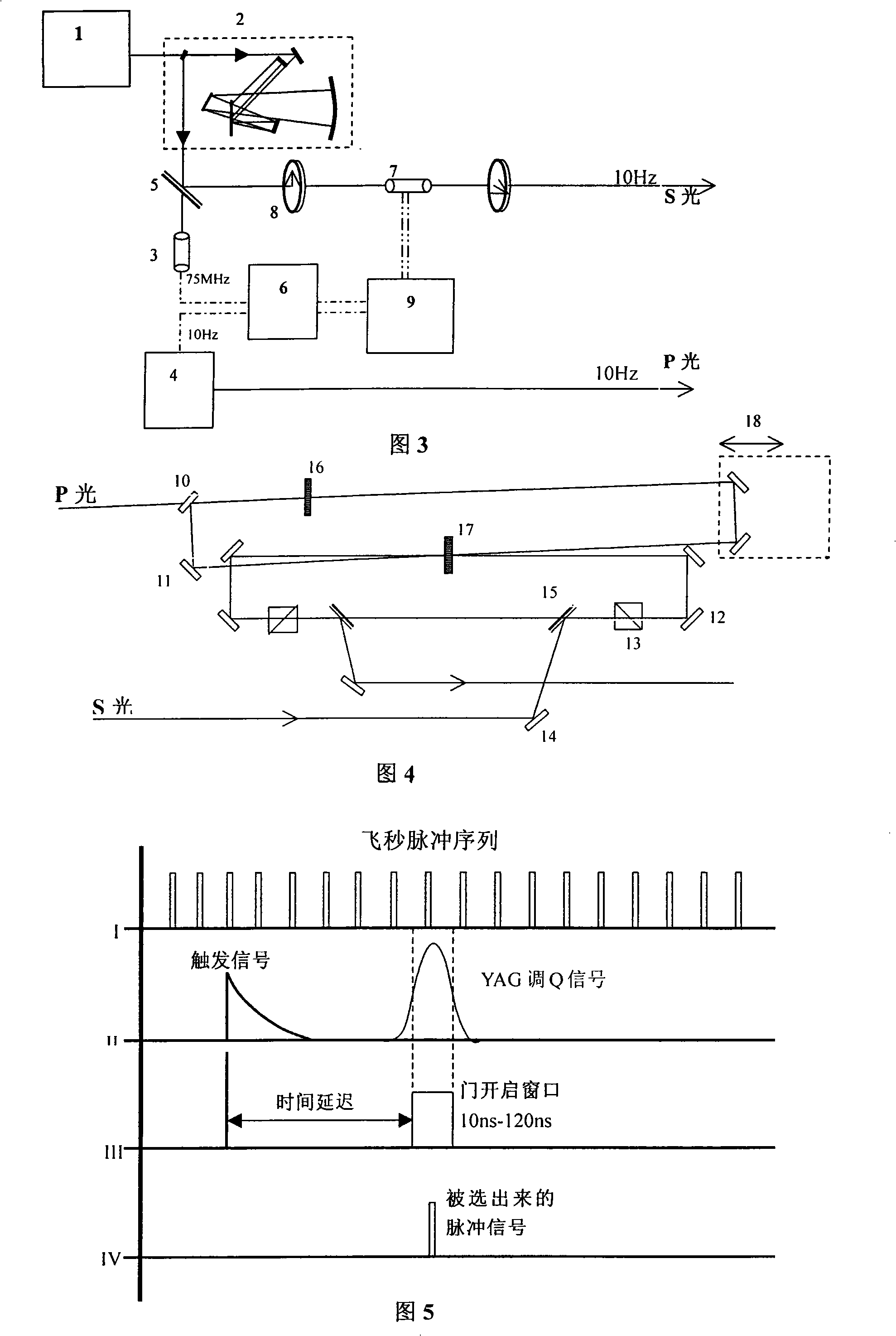
[0017] like figure 1 As shown in -5, the symbols in the figure respectively represent: τ is the time τ for the light to circulate in the cavity once determined by the cavity length, a is the leading edge of the pump pulse that first enters the cavity, and b is the pump pulse within the first two T periods. The intensity of the superimposed pump pulse, c is the intensity of the superimposed pump pulse in the first three T times, d is the pulse intensity after the final superposition and enhancement, e is the signal light before the parametric action, and f is the pump light before the parametric action Intensity, g is the signal light intensity distribution after the first parameter action, h is the pump light intensity distribution...


PUM


Abstract

The invention relates to a novel optical parametric chirped pulse amplification method which overlays and enhances original pump light in a cavity by making use of the structure of a ring cavity so as to enhance the power density of the pump light and then reuses the pump light by making use of optical path difference of signal light and the pump light in respective cavities thereof so as to improve transformation efficiency. At last, the method adopts a cavity dumping technique, chooses optimal parametric amplification times and controls the saturation effect during the parametric process to overlay and enhance the original pump light in the cavity. The method makes use of the structure of the ring cavity to ensure the pulse front edge and back edge of the pump light are overlaid in the cavity and has the advantages of making use of pumping source with wide pulse and high energy to obtain high energy burst pulse output and improving the transformation efficiency of the pump light to the utmost extent.

Description

technical field [0001] The invention relates to a novel optical parametric chirped pulse amplification method, which belongs to the ultrafast laser pulse amplification technology. The method combines the characteristics of multi-pass parametric amplification and intracavity superposition enhancement, and can realize the full utilization of pumping light energy, thereby Optimize conversion efficiency. Background technique [0002] High peak power and high single pulse energy are important means to study the interaction of matter under extreme physical conditions, so how to obtain ultrashort and intense laser pulses has become one of the hot research fields at home and abroad. At present, there are three main methods of optical pulse amplification: one is the chirped pulse (CPA) amplification method, which is to broaden the femtosecond seed optical pulse in the time domain, then amplify it through a laser gain medium, and finally use a compressor to compress the pulse width to...

Claims


Application Information

Patent Timeline
IPC IPC(8): H01S3/091H01S3/083H01S3/10H01S3/00
Inventor 许金山徐世祥丁良恩
Owner EAST CHINA NORMAL UNIV
Why Eureka
Try Eureka