Method of mounting elements inside a wind generator tower

A technology for installing components for wind power generators, applied in the field of installing components inside metal towers, can solve the problems of increasing tower wall thickness and reducing tower wall fatigue strength, and achieve the effects of reducing thickness, simplifying manufacturing and assembly processes, and avoiding costs

Inactive Publication Date: 2008-09-10
GAMESA INNOVATION & TECH SA
View PDF3 Cites 11 Cited by
  • Summary
  • Abstract
  • Description
  • Claims
  • Application Information

AI Technical Summary

Problems solved by technology

[0004] This type of fixture allows an increase in the thickness of the tower wall due to the reduced fatigue strength of the tower wall

Method used


Image

  • Method of mounting elements inside a wind generator tower
  • Method of mounting elements inside a wind generator tower
  • Method of mounting elements inside a wind generator tower

Examples


Embodiment Construction

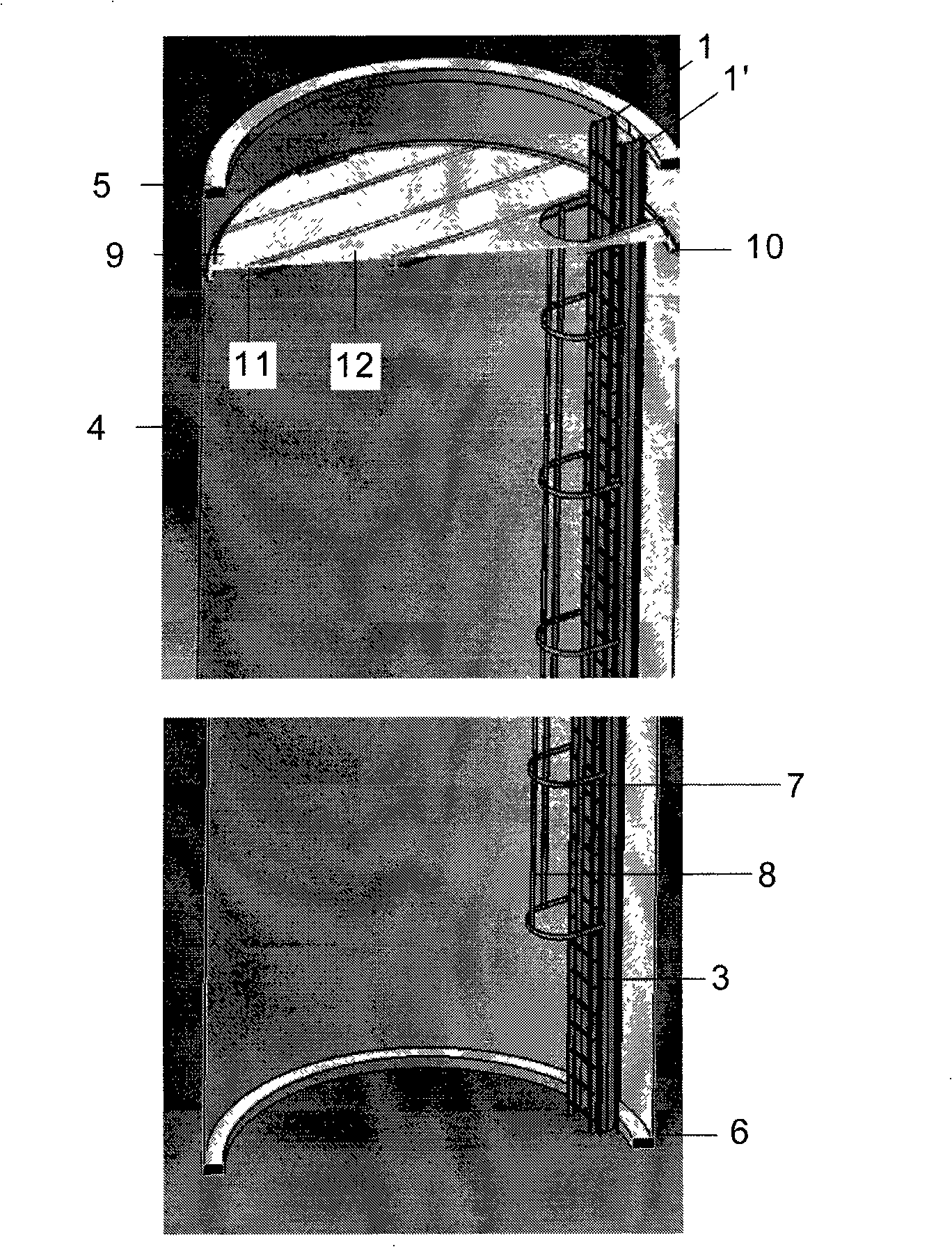
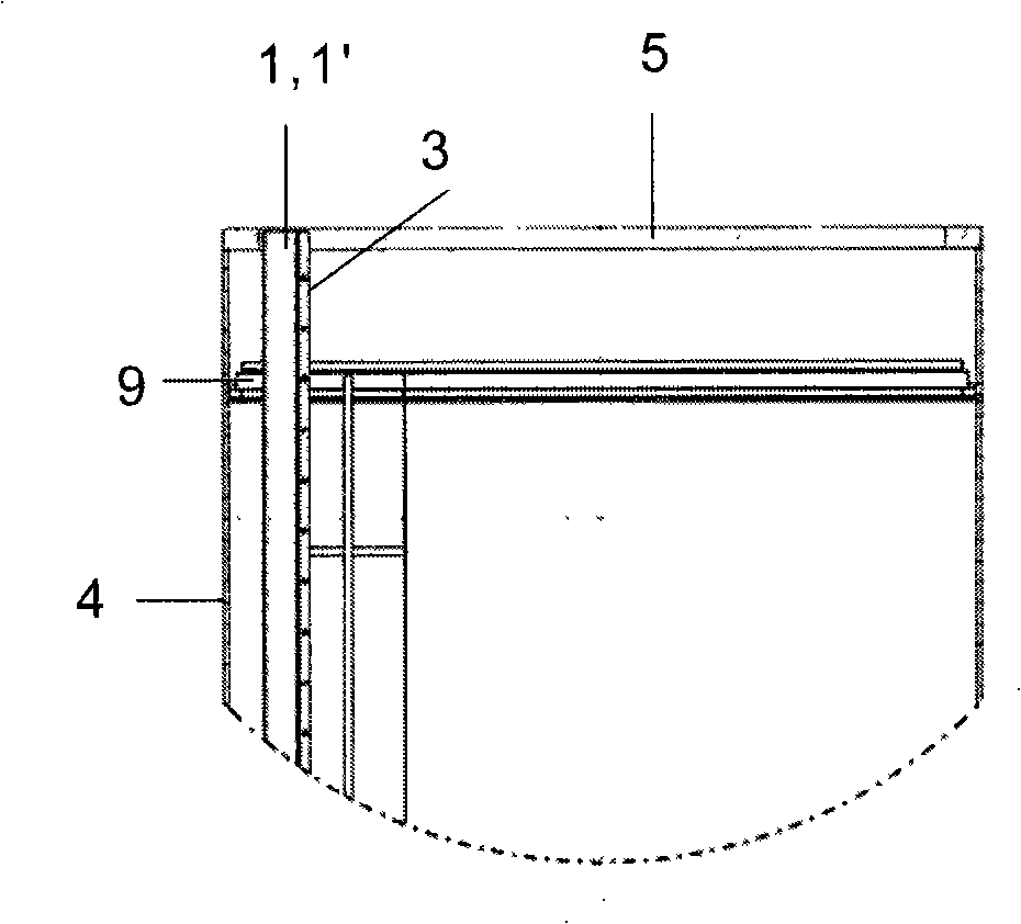
[0017] Metal wind turbine towers are formed by several segments 4 ranging in length from 10 m to 30 m, which are cylindrical bodies or tube cones (troncocónica) with an upper flange 5 and a lower flange 6 for contact with Other segment connections.

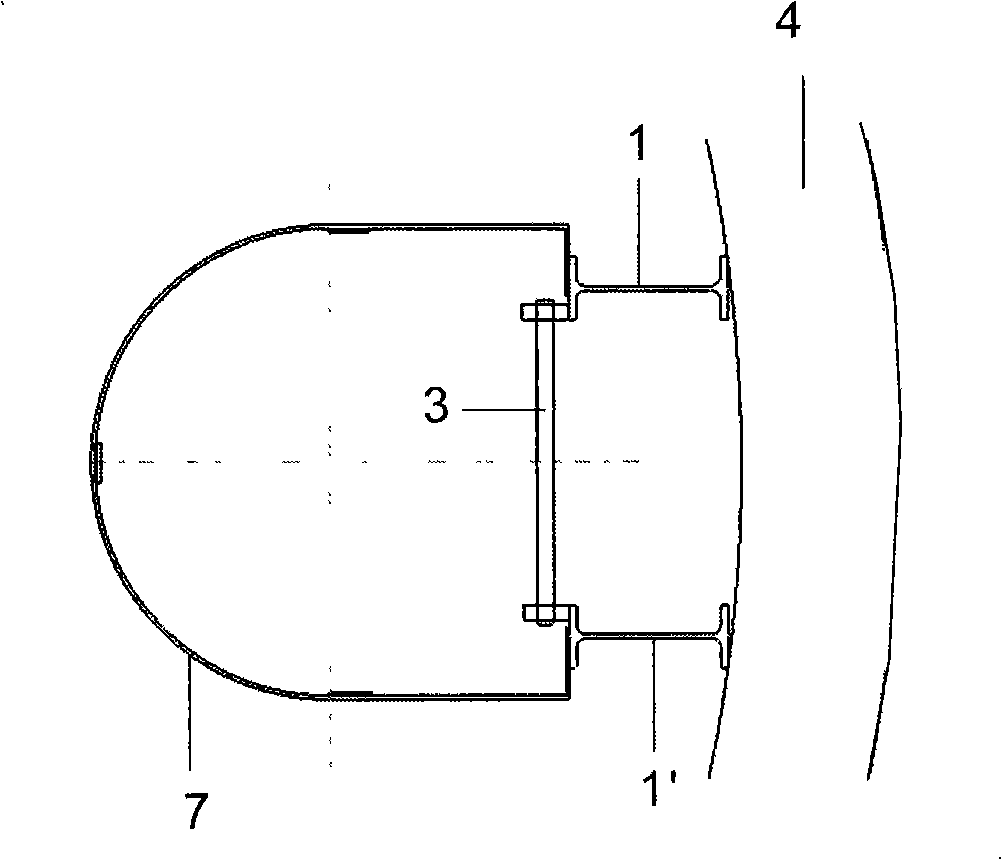
[0018] According to a first embodiment of the invention, the ladder 3 is not fixed directly to the section 4 of the tower, but to the two beams 1 and 1'.

[0019] Beams 1 and 1', preferably of double T-profile, are fixed to the upper flange 5 and the lower flange 6 of the section 4 of the tower in a manner parallel to the walls. They are fixed rigidly, for example by welding or bolts, to the upper flange 5 and horizontally to the lower flange 6 in a manner allowing longitudinal displacement.

[0020] This way of fixing the beams 1 and 1' allows for the bending of the section 4 caused by the working loads acting on the tower and likewise allows for expansion and contraction with temperature changes, whereas the aforementioned beam...


PUM


Abstract

The invention relates to a method of mounting elements inside a wind generator tower which is made from various different sections (4) of metal. According to the invention, elements such as ladders (3), platforms (9) and electric cables are fixed to auxiliary supports such as beams (2; 1, 1') or rings (10) which are in turn fixed to the above-mentioned sections (4) such as not to reduce the fatigue strength thereof.

Description

technical field [0001] The invention relates to a method for installing elements inside a tower of a wind power generator, in particular inside a metal tower constructed from a plurality of segments. Background technique [0002] Developments and innovations in the field of wind power generators in the last decade have led to increases in the size and power of the turbines of wind power generators, necessitating an increase in the height of the tower, and in order to achieve resistance performance, the tower must achieve thicker walls. These thicknesses are optimized by employing a structural calculation of the minimum tower wall thickness that can safely support the loads and vibrations experienced by the tower. [0003] Various elements must be kept inside the tower of a wind power generator, including ladders enabling various maintenance operations on said elements. In the known technique, these ladders are screwed onto rails which in turn engage connecting parts welded ...

Claims


Application Information

Patent Timeline
Patent Type & Authority Applications(China)
IPC IPC(8): F03D11/04F03D1/00
CPCY10T29/49826F03D11/04Y02E10/728F05B2240/912F03D13/20F03D80/80F03D80/85Y02E10/72F03D13/10F03D80/50
Inventor 何塞·伊格纳西奥·略伦特·冈萨雷斯
Owner GAMESA INNOVATION & TECH SA
Why Eureka
Try Eureka