Electrical machine having permanent magnets

A permanent magnet and rotor technology, applied in the direction of magnetic circuits, electromechanical devices, electrical components, etc., can solve the problem of increasing the axial length of the motor

Inactive Publication Date: 2008-09-10
SIEMENS MOBILITY GMBH
View PDF1 Cites 27 Cited by
  • Summary
  • Abstract
  • Description
  • Claims
  • Application Information

AI Technical Summary

Problems solved by technology

But this also increases the axial

Method used


Image

  • Electrical machine having permanent magnets

Examples


Embodiment Construction

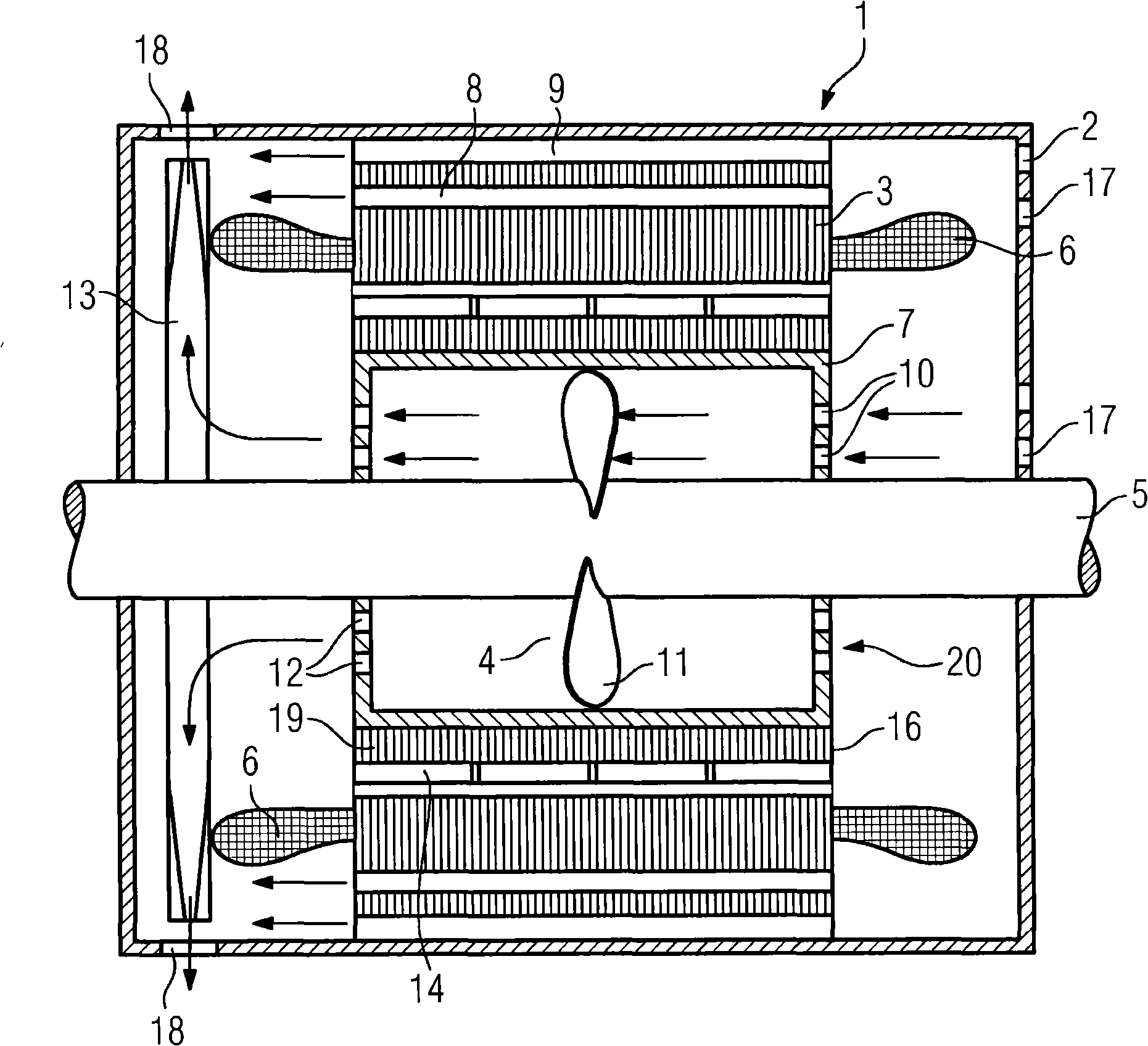
[0021] The drawing shows a schematic diagram of an electric machine 1 , in particular a permanent magnet synchronous machine arranged in a housing 2 . The electric machine comprises a stator 3 in which a winding system is arranged in a plurality of slots, this winding system forming an end winding 6 at the end face of the stator 3 . The winding system is in particular a three-phase winding system, in which both conventional winding techniques (ie short-pitch windings) and toothed coils can be used.

[0022] Tooth-wound coils are coils which each only wrap around one mechanical tooth of the stator 3 . The stator 3 is embodied as a lamination stack and comprises a plurality of cooling channels 8 extending substantially in the axial direction. A cooling channel 9 is also provided between the housing 2 and the stator 3, but in other embodiments, the cooling channel 9 is not a necessary component; in addition, even without the cooling channel 9, the working principle of the presen...


PUM


Abstract

Electrical machine (1) having a stator (3), which has axially extending cooling channels (8) in the laminate stack and/or cooling channels (9) extending between the stator and a housing, having a rotor (20), whose laminate stack (19) has an inner hole or is positioned on a spider structure (7) having an inner hole, wherein permanent magnets (14) are arranged in or on the laminate stack (19) of the rotor (20), wherein at least one axial-flow fan (4) is provided in the inner hole of the rotor (20), the air flow produced by said axial-flow fan, once it has passed through the rotor (20), by means of flowing through a suitable apparatus (13) achieves a nozzle effect which, owing to the venturi effect, brings about an air flow through the cooling channels (8) arranged in the stator (3). The remanence of the permanent magnets (14) is therefore positively influenced.

Description

technical field [0001] The invention relates to an electrical machine comprising a stator and a rotor, the stator comprising a plurality of axially extending cooling channels arranged in laminations of the iron core and / or arranged between the stator and the casing, the iron core of the rotor The laminations are arranged on the hub structure with an inner hole, wherein a plurality of permanent magnets are arranged in or on the iron core laminations. Background technique [0002] Attempts have been made to keep the permanent magnets of electric machines, especially electric machines with permanent magnets, at as constant a temperature level as possible, since the remanence of the permanent magnets is temperature-dependent. The temperature-dependent residual magnetism of the permanent magnets changes the magnetic flux of the motor, thereby reducing the induced voltage in generator mode and the producible starting torque in motor mode. [0003] The prior art is to use a radial...

Claims


Application Information

Patent Timeline
IPC IPC(8): H02K9/06H02K1/32H02K1/20H02K5/20H02K9/00H02K1/27
CPCH02K1/20H02K1/2706H02K1/32H02K9/06H02K5/207H02K5/203
Inventor 奥拉夫·柯纳
Owner SIEMENS MOBILITY GMBH
Why Eureka
Try Eureka