Cast-in-situ reinforcing steel bar concrete floor

A technology of reinforced concrete floor and reinforced concrete, which is applied to floor slabs, building components, buildings, etc., can solve the problems of troublesome production of hollow tubes, high cost, and increased cost of hollow floors.

Inactive Publication Date: 2008-09-17
湖南邱则有专利战略策划有限公司
View PDF0 Cites 0 Cited by
  • Summary
  • Abstract
  • Description
  • Claims
  • Application Information

AI Technical Summary

Problems solved by technology

In this way, the production of the hollow tube is troublesome and the cos...

Method used


Image

  • Cast-in-situ reinforcing steel bar concrete floor
  • Cast-in-situ reinforcing steel bar concrete floor
  • Cast-in-situ reinforcing steel bar concrete floor

Examples


Embodiment Construction

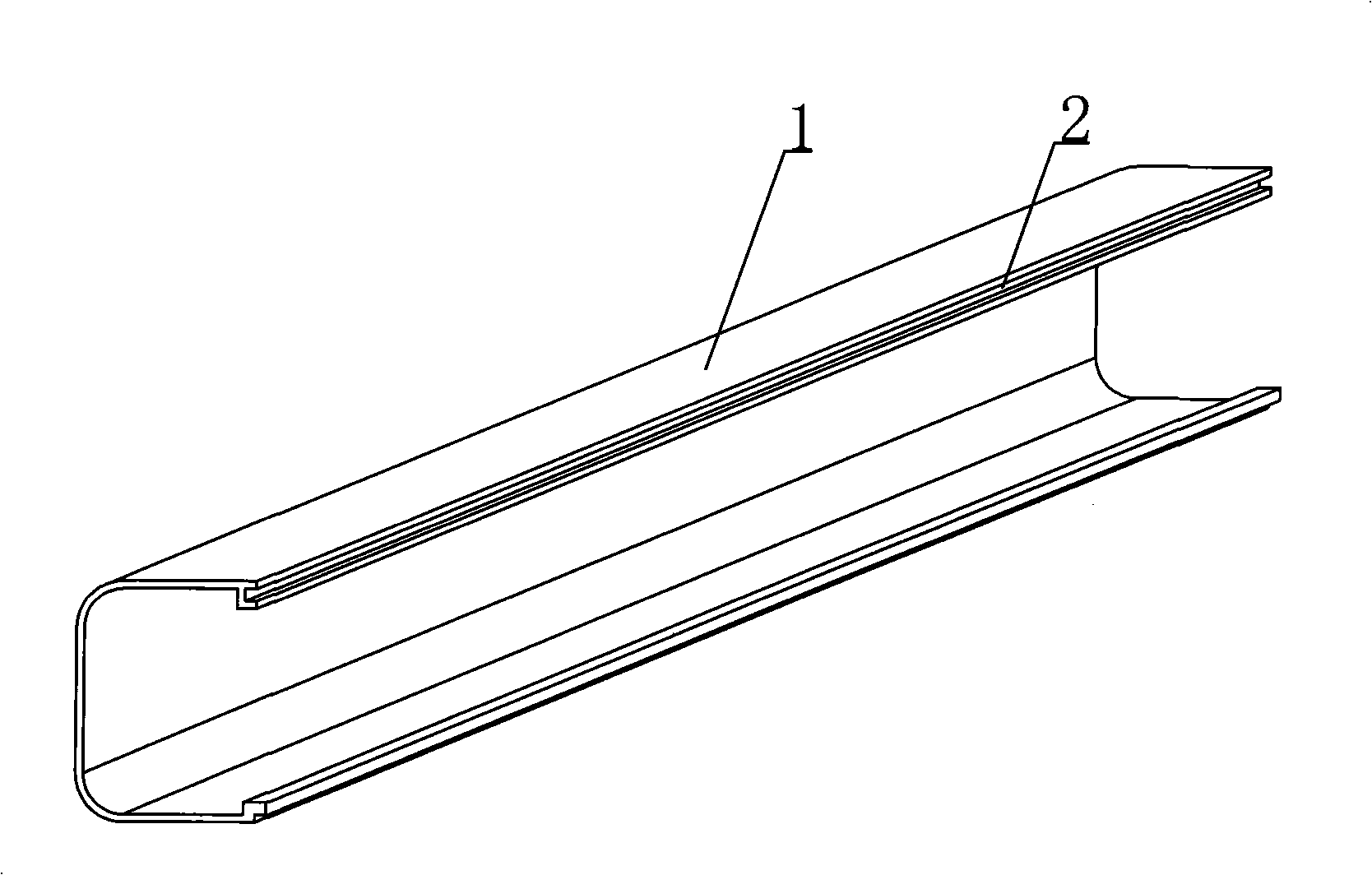
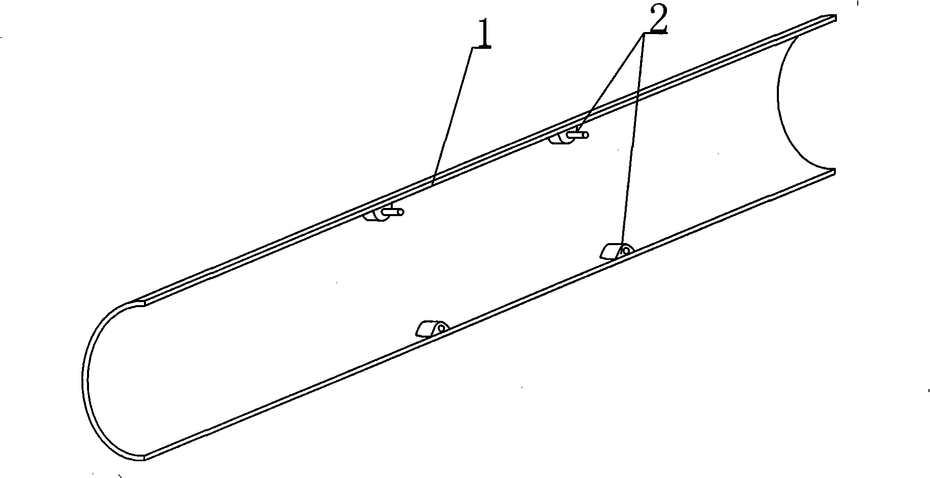
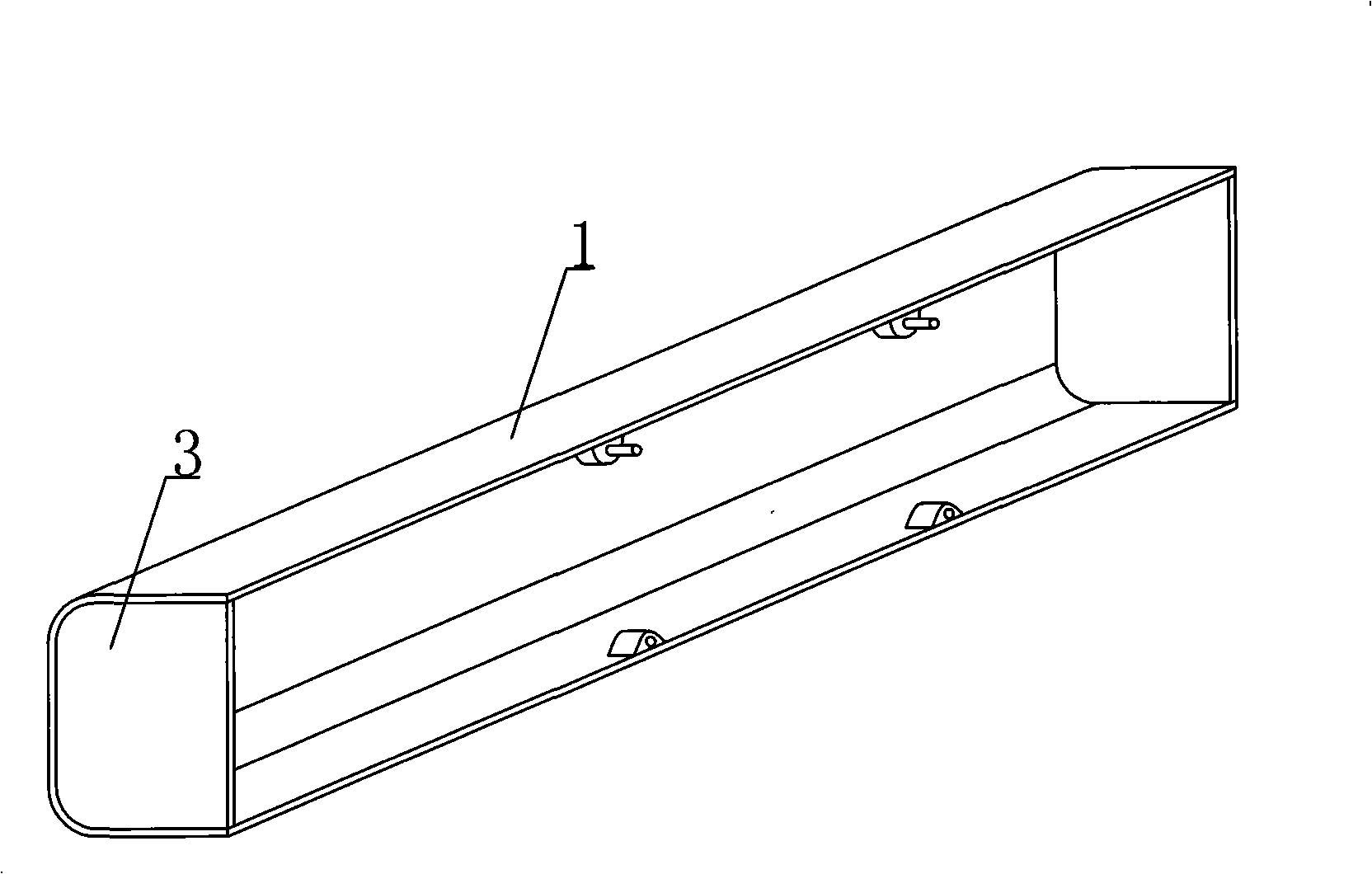
[0042] The present invention will be further described below in conjunction with the accompanying drawings and embodiments.

[0043]The present invention, as shown in the accompanying drawings, is characterized in that the hole-forming member is a combination component 1 that constitutes an integral cavity-forming component, and the combination component 1 is provided with a connecting piece 2 for combination. figure 1 It is a structural schematic diagram of Embodiment 1 of the present invention. In the accompanying drawings, 1 is an assembly part, and 2 is a connecting piece. In each accompanying drawing, those with the same number have the same description. Such as figure 1 As shown, the hole-forming member is a combined component 1 that constitutes an integral component for forming a cavity, on which there are joints 2 for combining with each other. The figure shows a half-side square-round tubular combined component, which can also be one-third or one third. Quarter-tubu...


PUM


Abstract

A cast-in-situ reinforced concrete floor plate comprises reinforced concrete and a hole-forming member, and is characterized in that the hole-forming member is an integrated member formed by combined parts (1) as a cavity, a connecting member (2) used for combining is arranged on the combined parts (1), end plates (3) are arranged on two ends of the combined parts (1) to form a basin-shaped combined member. The hole-forming member is formed by oppositely fastening the two basin-shaped combined members at the basin openings, fastening mechanisms are arranged at the fastened basin openings, the basin-shaped combined member has different external shapes. The floor plate is applicable to hollow floors, roofs, walls, soleplates and open-spandrel bridges of the cast-in-situ or pre-stress reinforced concrete, in particular to the hollow beamless floors.

Description

[0001] This application is a divisional application of an invention patent application with an application date of December 22, 2002, an application number of 02158263.7, and a title of "a component for forming holes in cast-in-place reinforced concrete". (1) Technical field [0002] The invention relates to a cast-in-place reinforced concrete floor slab. (2) Background technology [0003] At present, in the prior art, the hole-forming components of the cast-in-place hollow floor slab are permanent mandrels, such as paper tubes, plastic tubes, metal bellows, and lightweight materials for mandrels. These tubular mandrels or components are mainly considered to evacuate the concrete and reduce the weight of the floor slab. For example, the patent No. ZL99249775.8 applied by the applicant is a utility model patent named "fiber-reinforced thin-walled tube for filling cast-in-place reinforced concrete". It consists of a hard thin-walled tube and plugs at both ends. The head seals...

Claims


Application Information

Patent Timeline
IPC IPC(8): E04B5/36E04C1/00
Inventor 邱则有
Owner 湖南邱则有专利战略策划有限公司
Why Eureka
Try Eureka