Engine wind-guiding cover structure

A technology of wind deflector and engine, applied in the direction of air cooling, engine components, machines/engines, etc., which can solve the problems of reduced cooling wind, shortened service life of engine 1, impact of cooling wind, etc.

Inactive Publication Date: 2012-07-25
KYMCO
View PDF0 Cites 0 Cited by
  • Summary
  • Abstract
  • Description
  • Claims
  • Application Information

AI Technical Summary

Problems solved by technology

see again image 3 As shown, when the external cooling wind is forced by the fan 11 of the engine 1 into the air guide cover 2 through the air inlet 21 of the fan cover 23, since the cooling wind enters the air guide cover 2 in a tangential manner, the cooling wind will Hit the lower cover body of the wind guide cover 2, and the rotation of the lower half of the fan 11 will suck back the cooling flow to the lower cover body of the wind guide cover 2, so that a turbulent flow area A is formed in the wind guide cover 2, and The rotation of the lower part of the fan 11 will suck back the cooling air in the air guide 2, resulting in the reduction of the cooling air in the air guide 2, thereby reducing the cooling efficiency of the engine 1
[0004] The existing air guide cover 2 is obviously unable to effectively cool the engine 1 in a balanced manner, which will cause uneven cooling of the engine 1. If the uneven cooling is severe, some parts of the engine 1 will be deformed, and the engine 1 will be damaged. Reduced service life of engine 1

Method used


Image

  • Engine wind-guiding cover structure
  • Engine wind-guiding cover structure
  • Engine wind-guiding cover structure

Examples


Embodiment Construction

[0014] In order to understand the structure of the present invention and the effect that can be achieved more easily, it is described as follows in conjunction with the drawings:

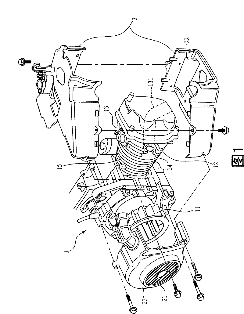
[0015] First, see Figure 4 As shown, the engine 3 of the engine air guide cover structure of the present invention includes a crankcase 31, a crankshaft 32 connected with the crankcase 31, a cylinder body 33 mounted on the crankcase 31, and a cylinder body 33 stretched in the cylinder body 33. The piston 34 , the cylinder head 35 arranged on the cylinder body 33 , and the cooling fan 36 driven by the crankshaft 32 . In addition, in order to increase the heat dissipation area of ​​the cylinder body 33 and the cylinder head 35, a plurality of cooling fins 331 and 351 arranged at intervals will be arranged on the cylinder body 33 and the cylinder head 35; Explosion, the gas pressure of its expansion will produce a thrust to push the piston 34 to reciprocate up and down. When the piston 34 descends, t...


PUM


Abstract

The invention relates to an engine wind guide cover structure, wherein a cylinder body and a cylinder head of an engine can be wrapped by the wind guide cover. The structure is characterized mainly in that a diversion mechanism is arranged under a covering of the wind guide cover; the diversion mechanism is provided with a body, a lateral gasket, and a bottom gasket; the body is provided with a diversion part, a steering part and a stopping part; cooling wind can be guided by the diversion part towards a spark plug; the steering part is an inclined plane; the cooling wind can be steered by the inclined plane to a cooling plate to cool the cooling plate evenly; the cooling wind can be effectively prevented by the stopping part from being absorbed back by a fan; the diversion mechanism is modularized and located on a cover cap under the wind guide cover; when the standard of the engine has some changes, only the diversion mechanism is needed to have a changed design, thus reducing the manufacture cost of the wind guide cover; through the diversion mechanism, an overlarge space of the wind cover can be eliminated to reduce a turbulence of the cooling wind and to effectively distribute the cooling air current; then the radiating effect of the whole body of the engine can be promoted, thus improving the service efficacy of the engine.

Description

technical field [0001] The present invention relates to a structure of an engine wind deflector, in particular to a structure that can replace a flow guiding mechanism without changing the design of the wind deflector. Background technique [0002] General forced air-cooled engines, such as figure 1 As shown, it is mainly composed of an engine power system 1 and a cooling windshield 2 passing through the engine power system 1. The cooling windshield 2 wraps the engine power system 1, and the external cooling wind is forced by the fan 11 of the engine 1. Yes, the air inlet 21 of the fan cover 23 enters the air guide cover 2, and through the guidance of the air guide cover 2, the cooling wind can blow to the engine 1, thereby dissipating the high temperature generated by the engine 1 through heat transfer. The exchange and heat balance function is exhausted from the air outlet 22 of the air guide cover 2, so as to make the engine 1 cool down. [0003] However, the highest te...

Claims


Application Information

Patent Timeline
Patent Type & Authority Patents(China)
IPC IPC(8): F01P1/02F01P5/06
Inventor 谢逸霖
Owner KYMCO
Why Eureka
Try Eureka