MR valve of non-rectilinear fluid course

A liquid flow channel and magnetorheological valve technology, applied in the field of hydraulic control valves, can solve the problems of lengthening the flow path length of electromagnetic rheological fluid, increasing the failure rate of magnetorheological valves, increasing the volume of magnetorheological valves, etc., to achieve Simple structure, convenient manufacturing and installation, and the effect of increasing the length of the flow channel

Inactive Publication Date: 2008-09-17
黑龙江科大科技开发有限公司
View PDF0 Cites 15 Cited by
  • Summary
  • Abstract
  • Description
  • Claims
  • Application Information

AI Technical Summary

Problems solved by technology

[0006] In order to overcome in the prior art, the damping device of the magnetorheological fluid provided to increase the resistance of the magnetorheological fluid channel in the magnetorheological valve has a complex structure, increases the volume of the magnetorheological valve, and increases the failure rate of the magnetorheological valve. Insufficient technology, the present invention proposes a magnetorheological valve structure with a non-linear liquid flow channel, so that the magnetorheologi

Method used


Image

  • MR valve of non-rectilinear fluid course

Examples


Embodiment Construction

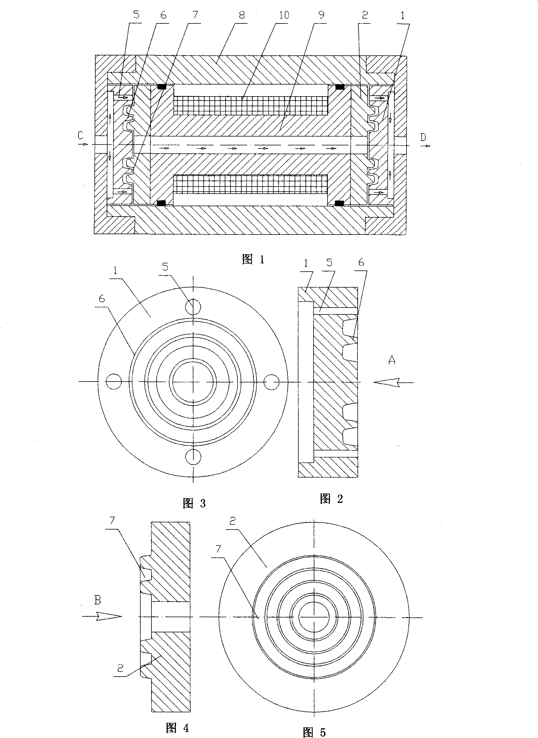
[0017] The technical solution adopted by the present invention to achieve the purpose of the invention is, referring to Figure 1, Figure 2 and Figure 3, Figure 4 and Figure 5, a magnetorheological valve with a non-linear flow channel, including: a valve body 8 , Coil support 9, excitation coil 10, positioning disk 1 and conductive disk 2, the excitation coil 10 is wound on the coil support 9, the conductive disk 2 is set at both ends of the coil support 9, the positioning disk 1 and the conductive disk 2 are coaxial Installation, a liquid flow channel is formed between the corresponding end faces of the positioning disc 1 and the guide disc 2, a set of concentric annular protrusions 6 are provided on the corresponding end faces of the positioning disc 1 and the guide disc 2, and the end faces of the guide disc 2 are arranged The annular groove 7 corresponding to the annular protrusion 6, the annular protrusion 6 and the corresponding annular groove 7, form a radial non-straight li...


PUM


Abstract

A MRF valve for non-linear flow channel mainly solves the problem that the magneto-rheological fluid conducts non-linear flow along the flow channel in the MRF valve. The MRF valve prolongs the flowing path length of the magneto-rheological fluid, improves the utilization rate of the magnetic line and increases the pressure difference of the controllable fluid of the magneto-rheological fluid under the same current intensity, thus achieving the aim of saving energy and reducing the size of the MRF valve. The technical scheme is to arrange a non-linear flow channel on the corresponding end surface of a positioning plate and a magnetic conductive disk. The MRF valve has advantages of simple structure, convenient manufacture and installation; the control range of the MRF valve is expanded without increasing the size of the MRF valve.

Description

Technical field [0001] The invention relates to a hydraulic control valve, in particular to a magnetorheological hydraulic control valve, an improved design of a magnetorheological fluid channel for a non-linear fluid flow channel magnetorheological valve. Background technique [0002] Compared with traditional hydraulic control valves, magnetorheological valves control the flow of magnetorheological fluid through the valve by controlling the magnitude of the excitation coil current. There are no moving mechanical parts. Compared with traditional mechanical valves, the magnetorheological valve controls the flow of magnetorheological fluid through the valve. The variable liquid control valve has the advantages of simple structure, small size, easy control, fast response speed, low operating noise, wear resistance, high reliability, and low cost. Magnetorheological valves are now widely used. [0003] The hydraulic control range of the magnetorheological valve has its own limitatio...

Claims


Application Information

Patent Timeline
IPC IPC(8): F15D1/00F16F9/53G05D7/03
Inventor 赵灿刘丹丹汤春瑞
Owner 黑龙江科大科技开发有限公司
Why Eureka
Try Eureka