Blowing control valve

A technology for controlling valve and valve stem, applied in the direction of lift valve, valve detail, valve device, etc., can solve problems such as excessive steam, loud noise, boiler blockage, etc.

Inactive Publication Date: 2010-06-23
WEITENG VALVE CO LTD
View PDF0 Cites 1 Cited by
  • Summary
  • Abstract
  • Description
  • Claims
  • Application Information

AI Technical Summary

Problems solved by technology

Either a lot of time is spent on the adjustment process, or the adjustment process also causes the boiler to block or consume too much steam
When the soot blower stops working, the high-temperature coal ash gas in the boiler flows back into the gun barrel, and combines with the condensed water in the gun barrel to become acidic. Long-term corrosion causes the gun barrel to rupture, and the soot blower cannot work, which not only affects the thermal efficiency of the boiler, but also causes the boiler Overheating work will affect the life of the boiler, and even cause the boiler to be scrapped. Therefore, a valve is needed to control the entry of steam. The existing technology uses a poppet valve to achieve the purpose of control. The poppet valve is a cut-off valve that only has a cut-off function. If the valve is not used correctly, too many failures can occur, boiler tube corrosion can occur, cleaning media is consumed, and other components in the sootblower can be endangered
The poppet valve is composed of valve body, valve disc, valve seat, valve stem, guide sleeve and other components. The guide sleeve is fixedly set on the outer ring of the valve stem, so it is difficult to change the flow area of ​​the soot blowing control valve, and it is impossible to adjust the pressure and flow. At the same time, the outer contours of the valve disc and the valve seat are generally transitioned at right angles. When the steam passes through the valve body, it will rub against the valve disc and the valve seat, which will generate a lot of noise and cause these parts to vibrate. The method of installing a muffler is adopted to reduce the noise; the soot blower connected to the air outlet of the poppet valve has always been corroded by the furnace gas in the boiler

Method used


Image

  • Blowing control valve
  • Blowing control valve
  • Blowing control valve

Examples


Embodiment Construction

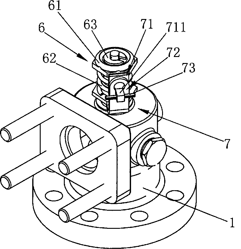
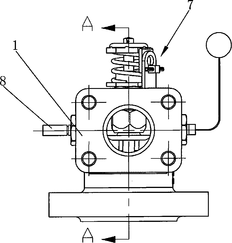
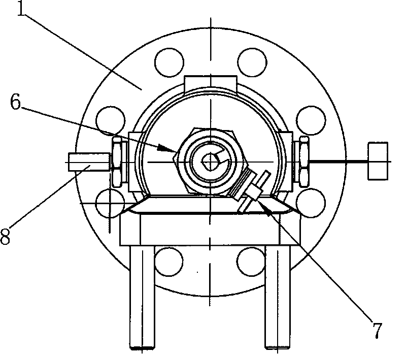
[0014] Such as figure 1 , 2 , 3, and 5, the embodiment of the present invention provides a soot blowing control valve, including a valve body 1, a valve disc 9, a valve seat 2, a valve stem 3, an adjustment ring 4, a guide sleeve 5, and a pressure adjustment device 6, The adjustment ring 4 is in the shape of "⊥", and there is a through square hole 41 in the middle. The adjustment ring 4 is located under the guide sleeve 5 and is sleeved on the valve stem 3. The lower end surface of the guide sleeve 5 corresponds to the upper end of the adjustment ring 4. Circular groove 51, the upper end of the adjustment ring 4 is set in the groove 51, and is threaded with the guide sleeve 5. Hole 41 fits. The pressure regulating device 6 includes an adjusting nut 61 and a pressure spring 62. The adjusting end 31 of the valve stem 3 is exposed from the upper end surface of the valve body 1. A through hole 611 is opened in the center of the adjusting nut 61, and the adjusting nut 61 passes t...


PUM


Abstract

The invention relates to an ash blowing control valve, which comprises a valve body, a valve flap, a valve holder, a valve handle, and a guide sleeve. The ash blowing control valve also comprises a reverse T-shaped adjusting ring. A square hole passes through the middle of the adjusting ring, the adjusting ring is positioned below the guide sleeve and sleeve on the valve handle, the lower end face of the guide sleeve is provided with a round groove corresponding to the upper end part of the adjusting ring, the upper end part of the adjusting ring is arranged in the groove and connected with the guide sleeve through threads, and the cross section of the part of the valve handle with adjusting ring is square and matched with the square hole of the adjusting ring. Compared with prior lift valve, the ash blowing control valve improved in the invention has an optimized and reasonable structure, and has cutting function as well as pressure and flow adjusting function in the control valve body.

Description

technical field [0001] The invention relates to a valve, in particular to a soot blowing control valve. Background technique [0002] Sootblowers require periodic readjustment of the blowing pressure in order to adapt to changing boiler conditions and cleaning requirements. A sootblower can take anywhere from two hours to a full day to adjust a built-in poppet valve. This adjustment program will become a project of 20-60 days for a mechanic who checks and adjusts the pressure sootblower. For this labor-intensive process, the following problem is more likely to occur. Either a lot of time is spent on the conditioning process, or the conditioning process also causes the boiler to clog or consumes too much steam. When the soot blower stops working, the high-temperature coal ash gas in the boiler flows back into the gun barrel, and combines with the condensed water in the gun barrel to become acidic. Long-term corrosion causes the gun barrel to rupture, and the soot blower ca...

Claims


Application Information

Patent Timeline
Patent Type & Authority Patents(China)
IPC IPC(8): F16K1/52F16K27/02
Inventor 王汉光狄九旺
Owner WEITENG VALVE CO LTD
Why Eureka
Try Eureka