Indoor light long-range control system based on Ethernet

A remote control system and remote control technology, applied in the field of indoor lighting remote control system, can solve the problems of remote control and other problems

Inactive Publication Date: 2008-09-24
JILIN UNIV
View PDF1 Cites 11 Cited by
  • Summary
  • Abstract
  • Description
  • Claims
  • Application Information

AI Technical Summary

Problems solved by technology

[0004] The technical problem to be solved by the present invention is to overcome the problem that the existing technology cannot achieve remote

Method used


Image

  • Indoor light long-range control system based on Ethernet
  • Indoor light long-range control system based on Ethernet
  • Indoor light long-range control system based on Ethernet

Examples


Embodiment Construction

[0021] The present invention is described in detail below in conjunction with accompanying drawing:

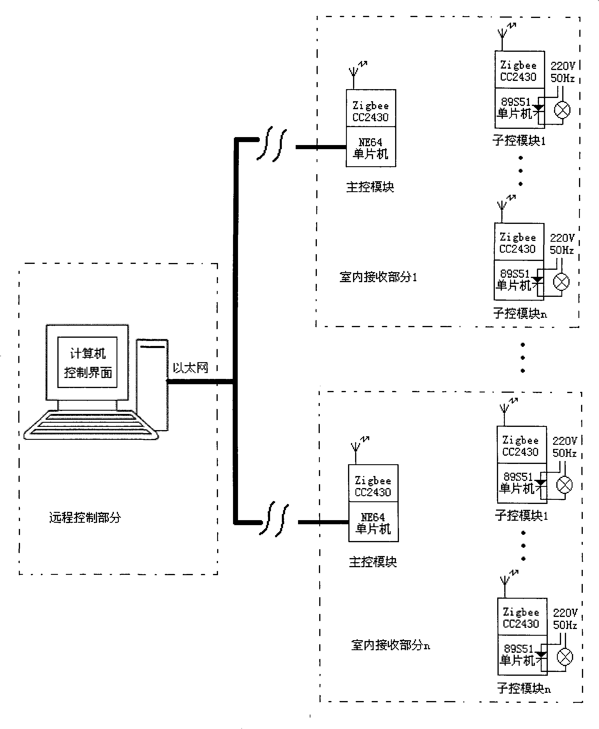
[0022] The Ethernet-based indoor lighting remote control system is mainly used for unified and centralized control of controlled lighting in certain places. For example, the user can detect and control indoor lamps in the home or other office and leisure places in the office. Users can check whether all the lamps in a relatively large place (a building) are turned off. If not, they can be controlled to turn off through the network, which avoids checking one by one and avoids the occurrence of unsafe incidents.

[0023] refer to figure 1 , the Ethernet-based indoor lighting remote control system includes a remote control part and at least one indoor receiving part (how many of the maximum N indoor receiving parts can be determined according to needs). The remote control part is a computer installed with the computer program of the control interface compiled by VB language, an...


PUM


Abstract

The invention discloses a remote controlling system for interior lighting based on the Ethernet, which aims at solving the problem that the interior lighting can not be controlled in a remote distance. The system includes a remote controlling part and at least one interior receiving part. The remote controlling part is a computer which is equipped with a computer procedure utilizing the VB language compilation to control an interface and is connected with the Ethernet. The interior receiving pert includes a main control module and at least one subsidiary controlling module. The main controlling module comprises an MC9S12NE64 single chip and a ZigbeeCC2430 main module. The MC9S12NE64 single chip is connected with the Ethernet. The main controlling module receives data information from the Ethernet and transmits the data information to the subsidiary controlling module in a way of wireless transmission. The subsidiary module comprises a ZigbeeCC2430 slave module, an 89S51 signal chip and a light-controlling circuit. The subsidiary module receives the order sent from the main controlling module in the way of wireless transmission for controlling the switch of the lights or the brightness of the lighting.

Description

technical field [0001] The present invention relates to a device for controlling indoor lighting, more specifically, it relates to a remote control system for indoor lighting based on Ethernet Background technique [0002] In the existing technology, the conduction time of the current flowing through the incandescent lamp can be changed by controlling the conduction angle of the thyristor so as to achieve the effect of changing the brightness of the light. One end of the silicon controlled rectifier is connected to the single-chip microcomputer through the photocoupler MOC3021, and the other end is connected to the circuits at both ends of the incandescent lamp. Through the timing program of the single-chip microcomputer, the conduction time of one end of the relay is changed, thereby changing the flow time of the current in the incandescent lamp at the other end, and controlling the brightness change of the incandescent lamp. But it cannot implement remote control on turni...

Claims


Application Information

Patent Timeline
IPC IPC(8): H05B37/02H04Q7/00
Inventor 陈万忠刘富张倬龚银银吴薇刘斌
Owner JILIN UNIV
Why Eureka
Try Eureka