Wireless intelligent cuisine apparatus, cuisine stove and accessories, cuisine device and working method

A cooking utensil and intelligent cooking technology, which is applied to cooking utensils, electric heating devices, instruments, etc., can solve the problems of not being able to fry or fry, not being able to ensure strict sealing and waterproofing, and not being able to reduce the labor burden, and achieve the effect of convenient cleaning

Inactive Publication Date: 2008-10-01
ZHUHAI UNITECH POWER TECH CO LTD
0 Cites 113 Cited by

AI-Extracted Technical Summary

Problems solved by technology

[0002] At present, the utensils capable of automatic cooking on the market all integrate the heating source and the pot body, such as electric rice cookers, electric stew pots, etc., and use their own fixedly stored cooking data to automatically control the cooking process. The utensils that can cook automatically cannot precisely control the temperature of the pot body, and cannot meet the requirements of cooking automation standards
Simultaneously, these cooking utensils are limited by its structure, can't effectively fry or stir-fry etc. for the culinary characteristics of Chinese dishes, are only suitable for cooking or stewing food
Therefore, this type of automatic cooking utensils cannot meet the cooking requirements for automati...

Method used

6) the microprocessor CPU of the intelligent controller of stove can not receive the data information transmitted by wireless communication module within a period of time, and microprocessor CPU sends to electronically controlled valve or heating element controller by drive circuit Turn off the small command to reduce the amount of gas or current; when the microprocessor CPU cannot receive the data information from the wireless communication module for a period of time, the microprocessor CPU sends a shutdown signal to the electronic control valve or heating element controller through the drive circuit. command, stop heating to prevent wasting energy when there are no utensils to be heated on the hob.
A kind of working method of wireless intelligent cooking device, wherein, described stove and cooking utensil all have wireless communication module and antenna, the temperature sensor signal on cooking utensil is transmitted by wireless communication module and antenna, and on stove The wireless communication module and antenna rece...

Abstract

The invention provides an intelligent cooking device which adopts a wireless communication way to transmit information between a stove and a cooking appliance which are separated, can accurately control the temperature of the cooking appliance and lead the cooking process to meet the requirements of automation and a working method thereof. The cooking device comprises the stove and the cooking appliance, wherein, the stove and the cooking appliance are arranged by adopting a separable way; the cooking appliance also comprises a temperature sensor, an electronic circuit, a wireless communication module, an antenna and a battery; the exterior of the cavity of the cooking appliance is also provided with a device used for arranging the temperature sensor, the electronic circuit, the wireless communication module, the antenna and the battery; the electronic circuit of the cooking appliance comprises a wireless low power consumption module; the stove also comprises an intelligent controller, the wireless communication module and the antenna as well as a heating element controller which controls the on and off of a heating element and the amount of output heat, and the heating element is connected with the heating element controller; the intelligent controller comprises a microprocessor CPU, a communication interface circuit and a drive circuit.

Application Domain

Technology Topic

Image

  • Wireless intelligent cuisine apparatus, cuisine stove and accessories, cuisine device and working method
  • Wireless intelligent cuisine apparatus, cuisine stove and accessories, cuisine device and working method
  • Wireless intelligent cuisine apparatus, cuisine stove and accessories, cuisine device and working method

Examples

  • Experimental program(3)

Example Embodiment

[0040] Example one:
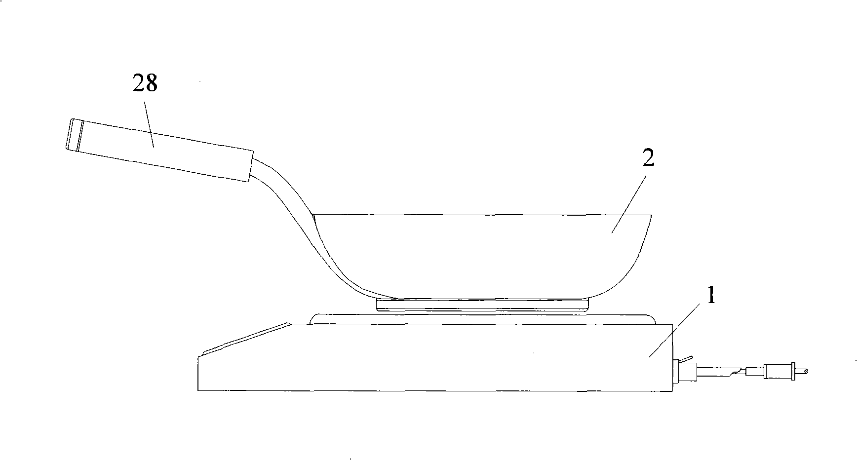
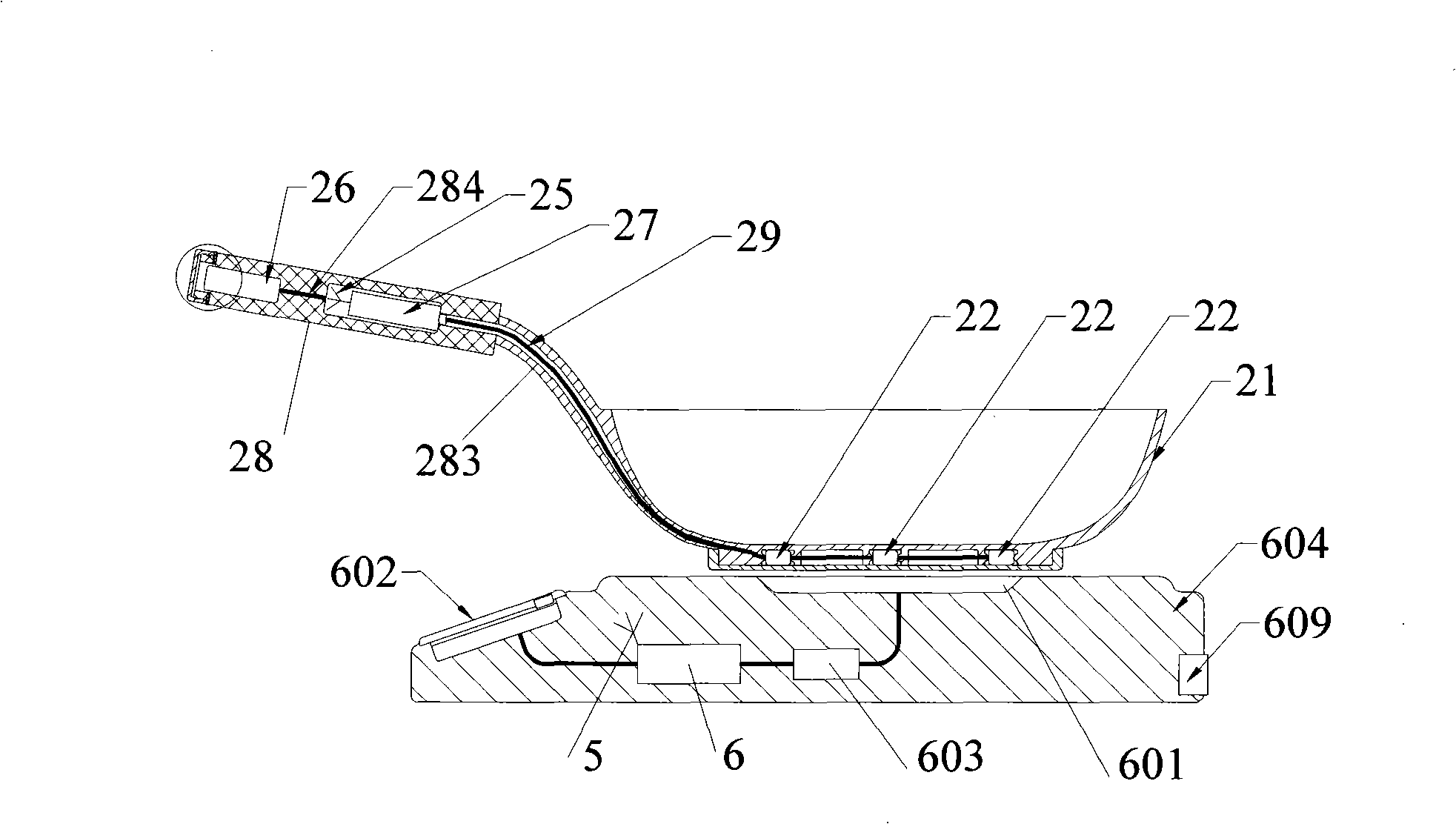
[0041] Such as figure 1 , figure 2 , image 3 , Figure 4 , Figure 7 , Figure 8 As shown, the wireless intelligent cooking device of this embodiment includes a stove 1 and a cooking appliance 2, wherein the stove 1 is provided with an intelligent controller 6, a wireless communication module 4 and an antenna 5, and the cooking appliance 2 is With a temperature sensor 22, an electronic circuit 23, a wireless communication module 24, an antenna 25 and a battery 26, the electronic circuit 23 includes a converter 231 and a control chip 232, the cooking appliance 2 is compatible with the stove 1 . The control chip 232 is a microprocessor or a programmable device capable of writing programs; the stove is an electric heating stove.
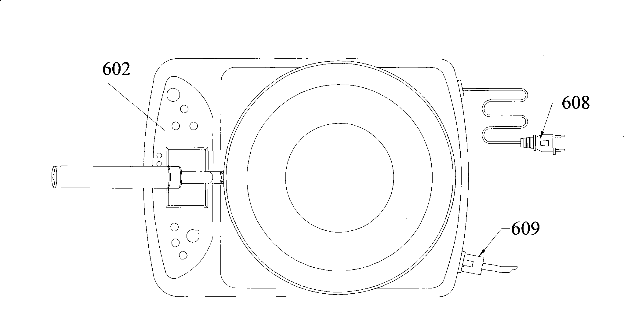
[0042] The stove 1 further includes a stove shell 604, a heating element 601, and a heating element controller 603, and the heating element 601 is connected to the heating element controller 603. The heating element 601 is located in the middle of the top surface of the stove 1.
[0043] The heating element 601 is an electric heating element, and the heating element controller 603 is a power controller, such as a thyristor.
[0044] The intelligent controller 6 on the stove includes a housing, a microprocessor CPU64, a communication interface circuit 61, a network interface circuit 65, a drive circuit 66, a button circuit 62, and an indication circuit 63. The microprocessor CPU64 and a communication interface circuit 61. The network interface circuit 65, the driving circuit 66, the button circuit 62 and the indicating circuit 63 are electrically connected, and the above-mentioned circuits are arranged in the housing.
[0045] The heating element controller 603 on the stove is electrically connected to the driving circuit 66 in the intelligent controller 6, and the wireless communication module 4 is electrically connected to the antenna 5 and the communication interface circuit 61 of the intelligent controller 6.
[0046] The cooking appliance also includes a pot body 21 and a handle 28. The outer wall of the pot body 21 is connected to the handle 28 and a closed cavity channel 283 is provided along the bottom of the pot body to the outer wall of the pot to the connection point of the handle 28. The airtight cavity channel 283 communicates with the airtight space of the handle 28, the electronic circuit 23, the wireless communication module 24 and the antenna 25 of the cooking appliance are arranged on an integral assembly 27, and the assembly 27 is arranged on the handle 28. The pot body 21 is provided with one or more airtight cavities, the temperature sensor 22 is arranged in the airtight cavity, and the temperature sensor 22 is insulated by heat-resistant The metal wire 29 is connected to the electronic circuit 23 on the assembly 27, the heat-resistant insulated metal wire 29 is arranged in the airtight cavity channel 283, and the wireless communication module 24 is electrically connected to the electronic circuit 23 and the antenna 25; the handle 28 is made of non-conductive materials.
[0047] The wireless communication module on the stove 1 and the cooking appliance 2 includes receiving and transmitting components, and the wireless communication module 4 on the stove 1 is adapted to the wireless communication module 24 on the cooking appliance 2.
[0048] The wireless smart cooking device is also provided with a man-machine interface 602, the man-machine interface 602 is provided with a button circuit 62, an indication circuit 63 with a display, indicator lights and sound elements, and the man-machine interface 602 is installed on the stove On the housing 604, a power socket 608 and a network interface socket 609 are provided at the rear of the stove housing 604.
[0049] The cooking appliance is also provided with a battery 26 which is installed in the battery box 280 at one end of the handle 28; one end of the battery box is provided with a conductive positive electrode, and the other end is provided with a conductive negative electrode. The electronic circuit 23 is electrically connected; one end of the battery box 280 is set as an end cover 281 of the handle, and conductive electrodes are arranged inside the end cover 281; the joint part of the detachable end cover 281 of the battery box 280 and the handle 28 is provided with a gasket 282; The battery 26 is electrically connected to the electronic circuit 23 through a wire 284.
[0050] The electronic circuit 23 of the cooking appliance 2 includes a wireless low power consumption module. The circuit diagram of the wireless low-power module is shown in Figure 11. The circuit of the wireless low-power module includes a module data processing unit U1, a data acquisition unit U2, a data wireless sending unit U3 and related peripheral devices; U1 is used as a wireless The CPU of the low-power module is the module data processing unit, responsible for the operation of the entire module system and low-power control; the interface between the module data processing unit U1 and the data acquisition unit U2 is a standard I 2 C bus. U1 receives sensor data from U2 and performs analysis and processing, and sends the data to U3, and sends the data out via U3. U2 is a data acquisition unit, through its pins 5, 6, 7 to measure the external state quantity, the interface between U1 and U2 is a standard I 2 C bus. During data collection, U1 controls G1 to turn on the power of U2 through pin 24, and then U1 through I 2 The C bus sends a data acquisition command to U2, U2 performs AD data conversion, and U1 passes I 2 The C bus reads the converted data from U2 and processes it, and sends the data to U3 for wireless transmission.
[0051] When sending data, U1 sets pin 9 to high level, and controls the VREG_EN of U3 to high level, so that the internal power regulator of U3 is turned on, and U1 sends the command to start U3 crystal oscillator X2 through the standard SPI interface. After waiting for U3 to work normally, configure the relevant working registers of U3, set the destination address and working channel, and then U1 writes the data into the data transmission buffer of U3 through the SPI interface, and turns on the data transmission function of U3. U3 passes the data through the inductor L2 The antenna matching circuit composed of, L3, L4 and capacitors C14, C12, C16, and C15 is sent out. U1 determines whether the data transmission of U3 is finished by detecting the state of pin 30 of U3. The low level means that the data transmission is completed; U1 waits for the data of U3 After sending, set VREG_EN to low level through pin 9 to turn off U3, and then U1 waits for the timer to trigger the next data collection and sending. At this time, the cooking appliance enters a low-power and power-saving mode.

Example Embodiment

[0052] Embodiment two:
[0053] Such as image 3 , Figure 5 , Figure 6 , Figure 7 , Figure 8 As shown, the difference between this embodiment and the first embodiment is that the stove is a gas stove, and the heating element is a gas stove.
[0054] The gas stove includes a furnace body 701, an intelligent controller 6, an electronic control valve 79, and an ignition circuit 706. The intelligent controller 6 is provided with a wireless communication module 4 and an antenna 5; the furnace body 701 also includes a gas hob 702 , Gas pipe 703, ignition pin 705, panel 602, network interface socket 609, power socket 608, the gas pipe 703 pipe-connects the gas hob 702 and the electric control valve 79, and the ignition pin 705 is electrically connected to the ignition circuit 706 , The network interface socket 609 and the power socket 608 are electrically connected to the intelligent controller 6; the electric control valve 79 is electrically connected to the drive circuit 66 on the intelligent controller 6, and is connected to the external air pipe interface 704 through the air pipe 703; the ignition The needle 705 is adjacent to the gas hole of the gas hob 702; the electronic control valve 79 includes a stepping motor 791 and a gas valve 792, and the output shaft of the stepping motor 791 is connected with the rotating shaft of the gas valve 792.
[0055] The ignition device and hob of the gas stove can adopt existing technology, and the electronic control valve can also adopt a gas valve with a stepping motor or a solenoid valve.

Example Embodiment

[0056] Embodiment three:
[0057] The stove shell of the wireless intelligent cooking device of this embodiment is provided with a network interface socket, the network interface socket is connected to the Internet, a telephone line or other communication networks, and the network interface socket is connected to the intelligent controller The network interface circuit is electrically connected; the intelligent stove controller includes a memory that can store various cooking method data.
[0058] A working method of a wireless intelligent cooking device, wherein the stove and the cooking appliance are equipped with a wireless communication module and an antenna, the temperature sensor signal on the cooking appliance is transmitted through the wireless communication module and the antenna, and the wireless communication on the stove The module and antenna receive the temperature signal from the cooking appliance and then transfer it to the intelligent controller. The intelligent controller compares the received temperature data with the set value and sends a control command to the heating element controller to increase or decrease the heating element The heat reaches the closed-loop control between the stove and the cooking appliance; when the cooking device is in a non-working state, the wireless communication module of the cooking appliance is in a dormant state; when the cooking device is in a working state, the cooking appliance’s The wireless communication module changes from the sleep state to the working state, and the temperature signal is transmitted outward through the wireless communication module and the antenna.
[0059] Such as Picture 9 As shown, a working method of a wireless smart cooking device, the working steps of the wireless smart cooking device include:
[0060] Step 1: After the ignition switch of the stove is turned on, start the smart controller and the wireless communication module on the stove. At this time, the wireless communication module is in the receiving state;
[0061] Step 2: Select the type or variety to be cooked on the panel buttons of the stove. This signal is transmitted to the microprocessor CPU through the keyboard circuit as the temperature and time setting value for this cooking.
[0062] Step 3: When the cooking appliance is placed on the heating element of the stove, as the temperature of the cooking appliance's pot body rises, the temperature sensor transmits a temperature signal to the electronic circuit. When a certain temperature is reached, the wireless communication module of the cooking appliance is in standby mode Turn to working state, and the temperature signal is transmitted outward through the wireless communication module and antenna;
[0063] Step 4: The antenna and wireless communication module of the stove receive the temperature signal sent by the cooking appliance, send it to the communication interface circuit of the intelligent controller, and send it to the microprocessor CPU for comparison with the set temperature setting value. When the temperature signal sent by the cooking appliance is higher or lower than the set value, the microprocessor CPU sends a control instruction to the drive circuit, and transmits it to the heating element controller to adjust the temperature of the heating element;
[0064] Step 5: When the cooking time reaches the time setting value, the microprocessor CPU sends a shutdown signal to the driver. After this signal is executed by the heating element controller, the heating element is turned off. At the same time, the microprocessor CPU also sends a signal to the indicating circuit to drive Indicator light and sound action;
[0065] Step 6: If the wireless communication module of the stove fails to receive the temperature signal from the cooking appliance within a certain period of time, the microprocessor CPU sends a signal to the driver to turn off the heating element controller; when it resumes receiving the signal from the cooking appliance After the temperature signal, the microprocessor CPU sends a control signal to the driver to resume normal heating; when the wireless communication module of the stove fails to receive the temperature signal from the cooking appliance within the set time, the microprocessor CPU sends a shutdown to the driver The signal of the heating element, the heating element is turned off;
[0066] Step 7: The work step is over.
[0067] The working steps of the wireless intelligent cooking appliance include:
[0068] Step 1: After the wireless smart cooking appliance is heated, the temperature sensor transmits a measurement signal to the converter;
[0069] Step 2: The converter converts the received measurement signal into a digital signal and then transmits it to the control chip. When the measured temperature signal exceeds the set value of the control chip, the control chip sends a start instruction to the wireless communication module to start the wireless transmission module and start working ;
[0070] Step 3: The wireless transmitting module receives the measurement signal from the control chip, and transmits the measurement signal through the connected antenna;
[0071] Step 4: The control chip sends a standby command to the wireless transmitting module to put the wireless communication module in a sleep state to save energy consumption. At the same time, the timer of the control chip starts timing;
[0072] Step 5: When the timer on the control chip reaches the set time (for example, 30 seconds), the control chip sends a start command to the wireless communication module again, and repeats the content of step 3 to step 5;
[0073] Step 6: When the temperature signal received by the control chip drops below the set value, the control chip no longer sends a start command to the wireless communication module, so that the wireless communication module is always in a sleep state to achieve the purpose of energy saving.
[0074] Step 7: The work step is over.
[0075] In the working method of the wireless intelligent cooking device, the operation steps of the panel include:
[0076] 1) Set the power switch to the on position and turn on the intelligent control circuit of the stove;
[0077] 2) Press the keys on the panel to select the cooking mode and parameters, and save the settings in the microprocessor of the intelligent controller;
[0078] 3) Press the start button. For gas stoves, the intelligent controller sends an ignition signal to the ignition circuit, and the ignition circuit generates high-voltage pulses to the ignition needle. At the same time, the intelligent controller sends an opening command to the electronic control valve through the drive circuit to allow the gas to pass through The valve enters the gas stove, the electric spark generated on the ignition needle ignites the gas, and the stove starts to heat; for the electric stove, the intelligent controller sends an opening command to the heating element controller through the drive circuit to make the electric heater start heating;
[0079] 4) The antenna on the smart controller of the stove and the wireless communication module receive the adapted radio signal. This signal is transformed into digital information containing temperature through the wireless communication module, and then transferred to the microprocessor CPU through the interface circuit, and saved The set value in the microprocessor CPU is compared, and the microprocessor CPU sends an open or close command to the electric control valve or heating element controller through the drive circuit, thereby controlling the gas flow through the valve or leading to electric heating The electric current of the device meets the requirements of adjusting the heating capacity;
[0080] 5) The microprocessor CPU in the intelligent controller of the stove compares the measurement parameters transmitted through the wireless communication module according to the preset time and temperature parameters, and keeps repeating the action in step 4 until the set time is reached. The microprocessor CPU sends a closing signal to the electric valve or heating element controller through the drive circuit, and at the same time, sends a start signal to the indicator light and sound element on the panel, and the sound and indicator light indicate the end of cooking;
[0081] 6) The microprocessor CPU of the intelligent controller of the stove cannot receive the data information transmitted by the wireless communication module for a period of time, and the microprocessor CPU sends a turn-off command to the electronic control valve or heating element controller through the drive circuit , Reduce the amount of gas or electric current; when the microprocessor CPU fails to receive the data information from the wireless communication module for a period of time, the microprocessor CPU sends a closing command to the electronic control valve or heating element controller through the drive circuit to stop Heating to prevent waste of energy when there is no utensil to be heated on the stove.
[0082] Such as Picture 10 As shown, the network working steps of the stove include:
[0083] Step 1: Connect the network interface of the stove to the Internet;
[0084] Step 2: The intelligent controller of the stove receives and saves the control parameters from the INTERNET network, such as data information such as temperature and time, through the network interface;
[0085] Step 3: The intelligent controller of the stove receives the instruction to start cooking from the INTERNET network through the network interface, and sends a control signal to the drive circuit to turn on the heating element;
[0086] Step 4: The intelligent controller of the stove judges whether the temperature signal from the cooking appliance is higher or lower than the control parameter requirements according to the control parameters obtained in Step 2, and automatically adjusts the heat of the heating element;
[0087] Step 5: The intelligent controller of the stove sends the cooking status parameters, such as starting cooking, about to end cooking, cooking end and turning off the heating element, and other information to the network interface and related equipment on the Internet;
[0088] Step 6: After the intelligent controller of the stove finishes cooking according to the set temperature and time and other control parameters, it sends a signal to the drive circuit to turn off the heating element;
[0089] Step 7: The intelligent controller of the stove sends out a signal that the cooking is completed to the indicating circuit, the indicator light flashes, and the sound sounds a reminder;
[0090] Step eight: the end of the work step.
[0091] The working method of the wireless intelligent cooking device, the network control operation steps:
[0092] a) After the microprocessor CPU receives the start instruction and cooking setting parameters from the INTERNET network through the network interface circuit, it sends an ignition signal to the ignition circuit. The ignition circuit generates high-voltage pulses to the ignition needle. At the same time, the intelligent controller passes through the drive circuit. Send an opening command to the electronic control valve, so that the gas enters the gas stove plate through the valve, the electric spark generated on the ignition needle ignites the gas, and the stove starts to heat;
[0093] b) The antenna on the smart controller of the stove and the wireless communication module receive the adapted radio signal. This signal is transformed into digital information containing temperature by the wireless communication module and then transferred to the microprocessor CPU, and then stored in the microprocessor. The set value in the CPU is compared, and the microprocessor CPU sends an instruction to open or close the electronically controlled valve through the drive circuit to control the gas flow through the valve to meet the requirements of adjusting the heating capacity;
[0094] c) The microprocessor CPU in the intelligent controller of the stove compares the measurement parameters transmitted through the wireless communication module according to the preset time and temperature parameters, and keeps repeating the action in step 4 until the set time is reached. The microprocessor CPU sends a closing signal to the electronic control valve through the drive circuit, and at the same time, sends the cooking end information to the Internet through the network interface circuit, including the cooking time;
[0095] d) When the microprocessor CPU of the intelligent controller of the stove fails to receive the data information from the wireless communication module for a period of time, the microprocessor CPU sends a turn-off command to the electronic control valve through the drive circuit to reduce gas; The microprocessor CPU fails to receive the data information from the wireless communication module for a period of time. The microprocessor CPU sends a closing command to the electronic control valve through the drive circuit to stop heating, so as to prevent the stove from having no utensils to be heated. Gas is wasted, and at the same time, a message to stop cooking is sent to the Internet through the network interface circuit, including interrupted cooking time, cooking time, etc.
[0096] For electric heating stoves, the difference with gas stoves is that the electric control valve is changed to a power controller, the gas stove plate is changed to an electric stove plate, the outer gas pipe interface is changed to a power socket, and the ignition circuit and ignition needle are removed, the furnace The appliance becomes an electric stove. The working steps are the same, the power controller adjusts the heating value of the electric heating plate.

PUM

no PUM

Description & Claims & Application Information

We can also present the details of the Description, Claims and Application information to help users get a comprehensive understanding of the technical details of the patent, such as background art, summary of invention, brief description of drawings, description of embodiments, and other original content. On the other hand, users can also determine the specific scope of protection of the technology through the list of claims; as well as understand the changes in the life cycle of the technology with the presentation of the patent timeline. Login to view more.

Similar technology patents

Water surface cleaning machine

InactiveUS20060102532A1Quick cleanEasy to cleanFloating sedimentation devicesFiltration separationMarine engineeringSolar cell
Owner:CADOTTE ROLAND JR

Shoes

InactiveCN102038315AEasy to cleanSolesEngineering
Owner:WUJIANG YUANXING SHOES

Classification and recommendation of technical efficacy words

Why Eureka
Try Eureka