Permanent magnetism synchronous electric machine test system and method

A technology of permanent magnet synchronous motor and test system, which is applied in the direction of motor generator test, measurement device, measurement of electrical variables, etc., can solve the problems of high test device requirements, rotor cross, complex straight-axis magnetic circuit, cross saturation, etc.

Active Publication Date: 2008-10-01
CHERY AUTOMOBILE CO LTD
View PDF0 Cites 36 Cited by
  • Summary
  • Abstract
  • Description
  • Claims
  • Application Information

AI Technical Summary

Problems solved by technology

Since permanent magnet synchronous motors are excited by permanent magnets, the test methods for the quadrature axis and direct axis inductance parameters are very different from those of electric excitation synchronous motors.
Moreover, the shape and position of the permanent magnets in the permanent magnet synchronous motor are various, the rotor AC and direct axis magnetic circuits are extremely complex, and the inductance parameters are not only related to the saturation of the magnetic circuit, but also the phenomenon of cross saturation between the AC and direct axis magnetic circuits
The commonly used DC attenuation method and voltage integration method have relatively high requirements for test equipment and are relatively complicated.

Method used


Image

  • Permanent magnetism synchronous electric machine test system and method
  • Permanent magnetism synchronous electric machine test system and method
  • Permanent magnetism synchronous electric machine test system and method

Examples


Embodiment Construction

[0029] Referring to the accompanying drawings, through the description of the embodiments, the specific implementation of the present invention, such as the shape, structure, mutual position and connection relationship between each part, the function and working principle of each part, and the test method etc., to make further detailed descriptions to help those skilled in the art have a more complete, accurate and in-depth understanding of the inventive concepts and technical solutions of the present invention.

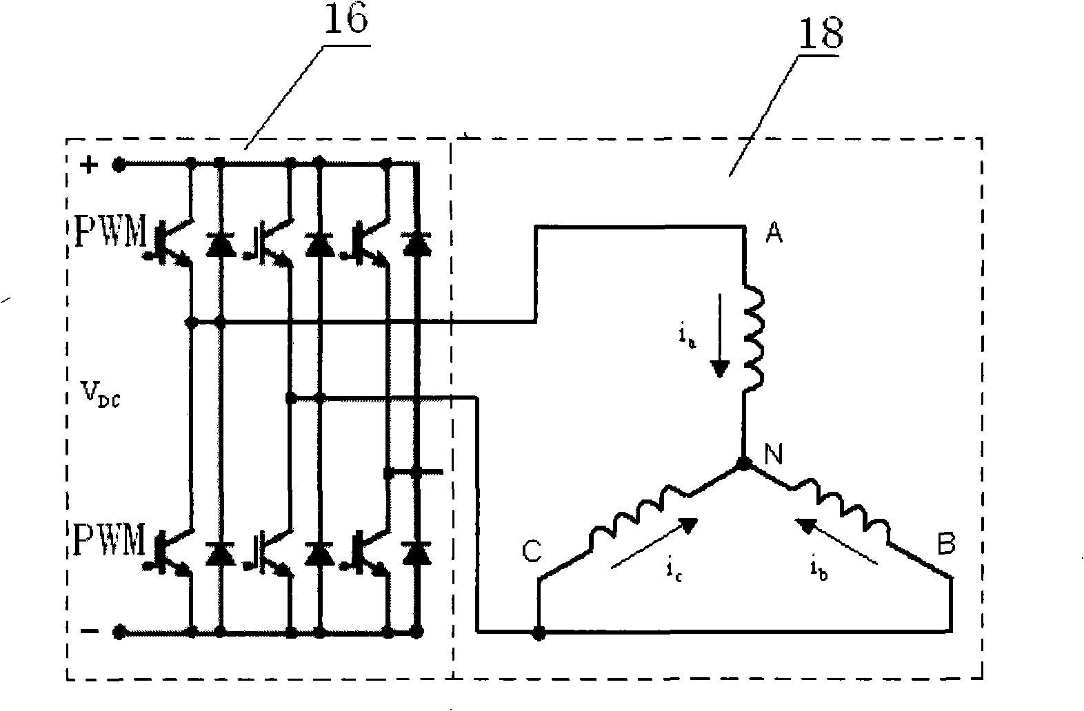
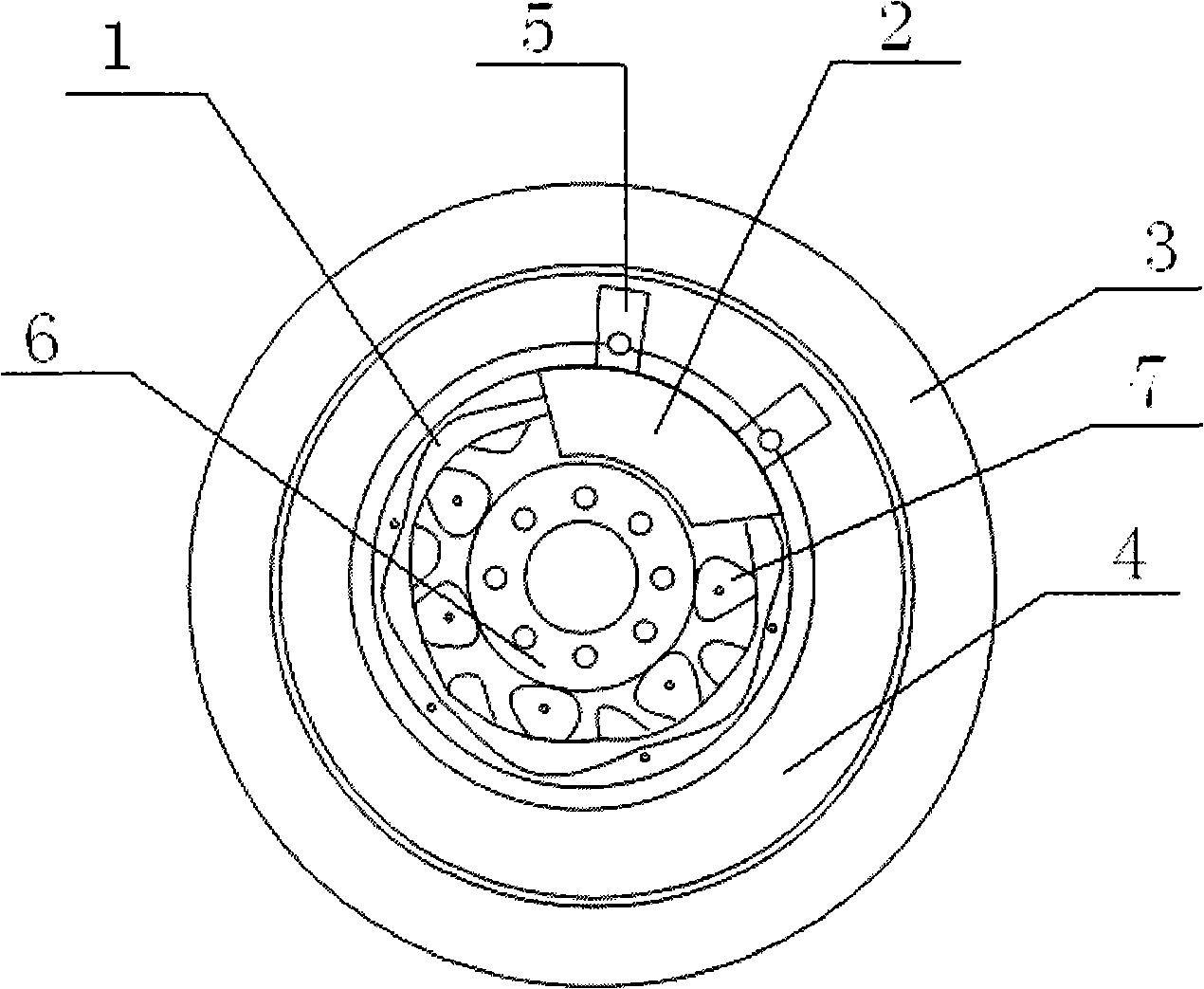
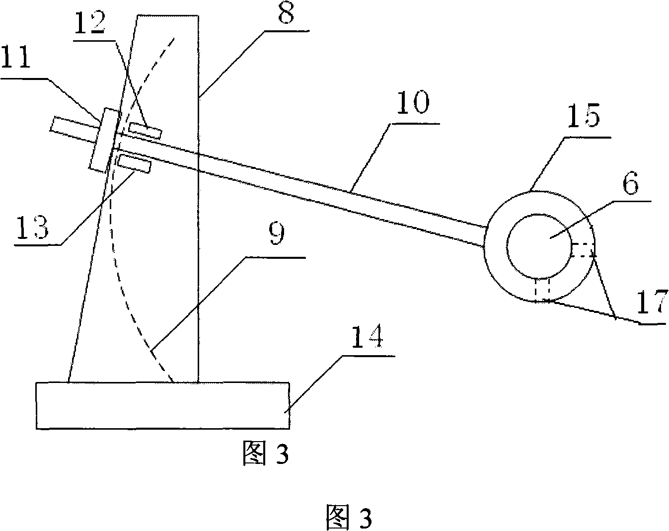
[0030] Such as figure 1 , figure 2 , shown in Fig. 3, a kind of permanent magnet synchronous motor testing system comprises inverter (16), permanent magnet synchronous motor, motor controller, temperature sensor, A phase of synchronous motor stator winding 18 and inverter 16 first The bridge arms are connected, the B phase and the C phase are short-circuited and then connected to the second bridge arm of the inverter 16, and the third bridge arm is suspended. One ...


PUM


Abstract

The present invention discloses a permanent magnet synchronous machine test system and a test method thereof. The test system comprises an inverter, a permanent magnet synchronous machine, a test computer and a temperature sensor. The invention is characterized in that the side of the permanent magnet synchronous machine is provided with a rotor position sensor which is connected with the test computer through a DSP chip. The rotating axis of the rotor is also connected with a rotation-blocking device. As the test system and test method are adopted, the inductor parameter measurement of the permanent magnet motor is executed through the rotor position sensor and the rotation-blocking device which fixes the position of the magnetic pole of the rotor. The position of the rotor is detected through a device which fixes the position of rotor with simple regulation and a DSP chip. The rotor of electric machine is finally fixed to the test position through a method of testing together with regulating. The inductor parameter test is realized through a voltage integrating method. Compared with prior art, the invention uses a simple device and uncomplicated method for realizing an accurate measurement to the inductor parameter of the permanent magnet synchronous machine.

Description

technical field [0001] The invention relates to a motor testing device, in particular to a test coefficient and a test method of an embedded permanent magnet synchronous motor. Background technique [0002] The direct-axis and quadrature-axis inductances of permanent magnet synchronous motors have a great influence on the steady-state and dynamic performance of permanent magnet synchronous motors, and the accuracy of direct-axis and quadrature-axis inductance parameters is not only important for predicting torque and field weakening performance but also for design Control system design for maximum efficiency, power factor, etc. is critical. The effect of magnetic saturation is usually accounted for in terms of inductance that varies with inductance. Therefore, it is very important to determine the inductance parameters of the direct axis and the quadrature axis. At present, a variety of techniques are used to predict the winding inductance, such as the finite element metho...

Claims


Application Information

Patent Timeline
Patent Type & Authority Applications(China)
IPC IPC(8): G01R31/34G01R27/26
Inventor 谢美娟
Owner CHERY AUTOMOBILE CO LTD
Why Eureka
Try Eureka