Glue solution injector driven by electromagnetic expulsive force

A technology of electromagnetic repulsion and injectors, which is applied in the direction of liquid injection devices, injection devices, electric solid devices, etc., can solve the problem of inability to adjust the movement stroke and spring preload, difficulty in realizing the gap between the electromagnet and the armature, and no design preload Adjust the knob and other issues to achieve the effects of shear thinning and micro glue injection, size reduction and service life improvement

Inactive Publication Date: 2008-10-08
CENT SOUTH UNIV
View PDF0 Cites 3 Cited by
  • Summary
  • Abstract
  • Description
  • Claims
  • Application Information

AI Technical Summary

Problems solved by technology

There is a U.S. patent related to this, which proposes a design scheme of electromagnetic suction-driven injection distributor, which does not improve the shortcomings of traditional pneumatic injection distributors and still has the following disadvantages in its structure: First, due to the design As a whole, it is difficult to achieve a small gap between the electromagnet and the armature; second, there is no limit pin designed, and the spray needle directly collides with the base, making the spray needle easy to damage; third, there is no design preload adjustment knob, Can not adjust the movement stroke and spring preload

Method used


Image

  • Glue solution injector driven by electromagnetic expulsive force
  • Glue solution injector driven by electromagnetic expulsive force

Examples


Embodiment Construction

[0026] The specific implementation manner of the present invention will be described in detail below in conjunction with the accompanying drawings.

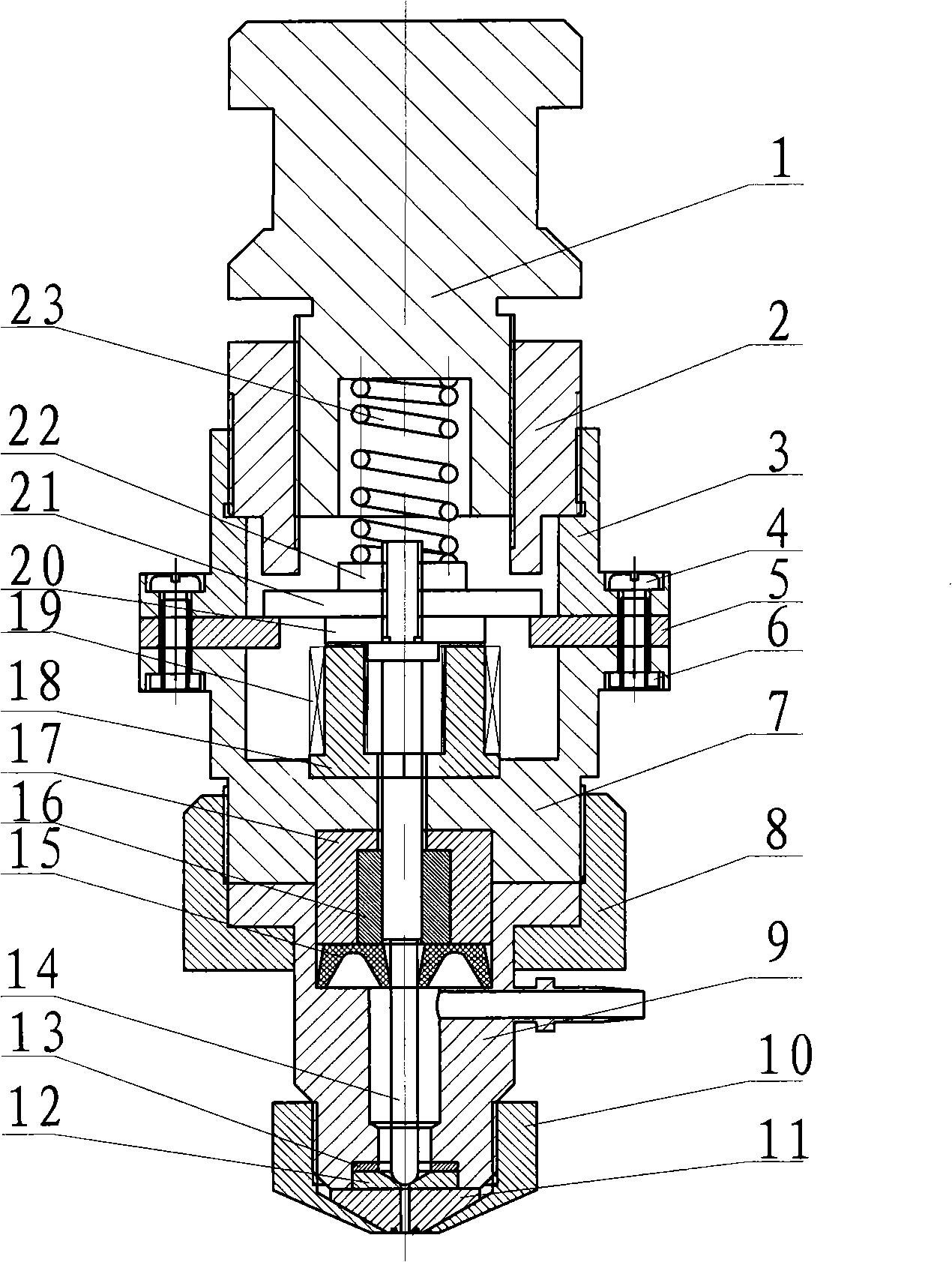
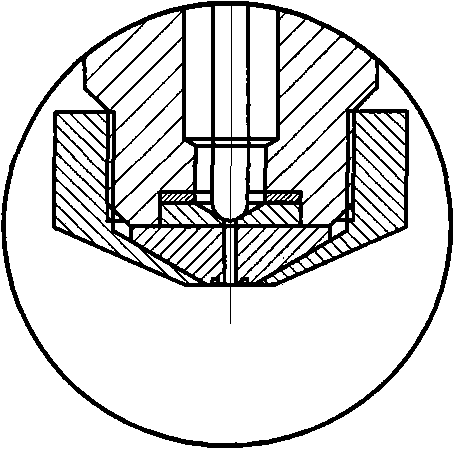
[0027] See attached figure 1 , 2 , the present invention --- a glue injector driven by electromagnetic repulsion, including a nozzle 11, a spray needle 14, a glue cavity 9, a thermal control body 10, a spring pretensioning device for a spray needle, and an electromagnet,

[0028] The needle spring pre-tensioning device includes a pre-tightening force adjustment knob 1, a stroke adjustment knob 2, and a pre-tightening spring 23; the lower end of the pre-tightening force adjustment knob 1 is provided with a cavity for placing the pre-tightening spring 23, and the outer peripheral surface Threads are provided on the top and screwed into the internally threaded hole of the stroke adjustment knob 2, and the outer circumference of the stroke adjustment knob 2 is provided with threads;

[0029] The electromagnet includes an upper conn...


PUM


Abstract

A glue ejector driven based on electromagnetic expulsive force comprises a nozzle, a spray needle, a glue cavity, a thermal cavity, a spray needle spring pretightening device and an electromagnetic body. The pray needle spring pretightening device comprises a pretightening force adjusting knob, a stroke regulating knob and a pretightening spring; the electromagnetic body comprises an upper connection body, a location chock block, a lower connection body, a magnet core, a loop, a gag bit, an adjustable baffle and a pretightening nut; the invention leads an electromagnet and the gag bit to exclude mutually by controlling the galvanizing voltage of the electromagnet to drive the spray needle to move upwards and compress the spring, then the spray needle restores under the action of the spring; thereby leading the spray needle to reciprocate, so as to reach the aim of spraying glue. The glue ejector of the invention has the advantages of simple structure, convenient use, adjustable spraying speed and glue spraying amount, long service life, which is suitable for industrialization manufacture, is capable of replacing the existing spring-pneumatic drive glue spraying system and is suitable for the sealing and packaging of micro-electric chips in particular.

Description

technical field [0001] The invention discloses a glue spraying device, in particular to a glue injector driven by electromagnetic repulsion, relates to the technical field of microelectronic equipment, and is mainly suitable for microelectronic chip packaging. Background technique [0002] Glue jetting is a new type of microelectronic packaging technology. In the existing technical field, the glue spraying equipment used for microelectronic packaging is mainly based on the pneumatic glue spraying equipment of Asymtek Company. It controls the high-pressure air flow in and out through the air control valve to push the driver piston to move up and down, thereby pushing the injection needle to reciprocate, and realizes the injection process of extruding glue. The driving force provided by the existing pneumatically driven injector is small, and at the same time, because the needle directly collides with the base, the material and size of the needle are greatly limited, and the ...

Claims


Application Information

Patent Timeline
Patent Type & Authority Applications(China)
IPC IPC(8): B05B9/04H01L23/28
Inventor 邓圭玲王军泉谢敬华彭志勇
Owner CENT SOUTH UNIV
Why Eureka
Try Eureka