
Composite material prick pipe structure wind load simulation test method

A simulation test and composite material technology, applied in the field of simulation test research, to achieve the effects of reliable results, short test period and simple operation

Active Publication Date: 2008-10-08
725TH RES INST OF CHINA SHIPBUILDING INDAL CORP
View PDF0 Cites 12 Cited by
  • Summary
  • Abstract
  • Description
  • Claims
  • Application Information

AI Technical Summary

Problems solved by technology

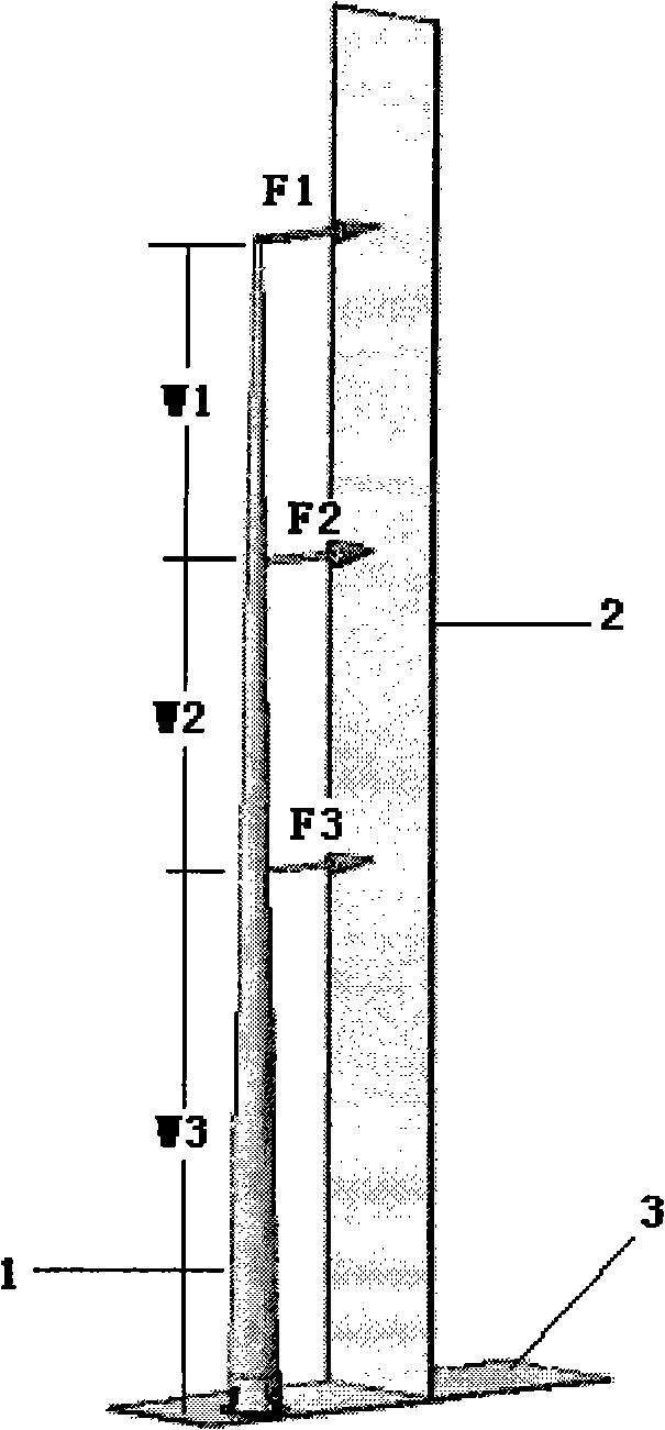
[0004] The purpose of the present invention is to propose a wind load simulation test method for a composite tapered pipe structure, which is used to replace the traditional wind tunnel test, solve the problem of wind load deflection simulation tests for composite tapered pipe structures such as chimneys, utility poles and antennas, and The method has the characteristics of simple operation, short test period, low cost and high reliability

Method used


Image

  • Composite material prick pipe structure wind load simulation test method
  • Composite material prick pipe structure wind load simulation test method
  • Composite material prick pipe structure wind load simulation test method

Examples


Embodiment 1

[0025] The deflection test of a utility pole with a composite tapered tube structure, length 8m, top diameter 30mm, bottom diameter 150mm, wind speed 45m / s.

[0026] ① Calculation of the wind load force on the utility pole with tapered tube structure

[0027] The load at the bottom of the pole is q max = π × 0.15 × 45 2 6400 = 0.149 kN / m

[0028] The load on the top of the pole is q min = π × 0.03 × 45 2 6400 = 29.8 N / m .

[0029] ② Determination of the loading positio...


PUM


Abstract

The invention belongs to the simulation research field. A proposed wind load simulation research method for a composite material conical tube structure comprises steps as follows: firstly obtaining the distribution of the trapezoidal load on the conical tube structure, determining the load position of central concentrated load, determining the central concentrated load, the flexivity of the conical tube structure, measuring and leveling the primary standard to conduct flexivity test. Adopting a method of local load through exerting multipoint instead of wind tunnel trial to measure the flexivity of the conical tube structure under certain wind speed, the invention has the advantages of simple operation, short test period, low cost and reliable result, besides, the invention not only can be used for the wind load simulation research method for chimney, telegraph pole and antenna conical tube structure composite materials, but also can be used for the wind load simulation research method for column-shaped and beam-shaped composite material structures, having prominent military and economic benefits.

Description

technical field [0001] The invention belongs to the field of simulation test research, and mainly proposes a wind load simulation test method for a composite tapered tube structure. Background technique [0002] With the gradual recognition of the performance of composite materials, various types of composite materials have been continuously applied in various fields of the national economy, including chimneys, utility poles and antennas and other tapered tube structure composite products, which generally use cone The tube structure, whose length ranges from one or two meters to more than one hundred meters, has high technical requirements for the product's own weight, deflection and damage under a certain wind speed. [0003] For a long time, wind load tests are usually carried out in wind tunnels. The cost of wind tunnel tests is high and the cycle is long, which is not conducive to the control of cycle and cost during the product development process. In addition, these pr...

Claims


Application Information

Patent Timeline
IPC IPC(8): G01M9/00
Inventor 郑劲东樊晓斌张兴刚
Owner 725TH RES INST OF CHINA SHIPBUILDING INDAL CORP
Learn More