Simulation platform and test method for flow field arrangement structure of flue gas denitration apparatus

A technology of flow field distribution and simulation platform, applied in teaching models, educational appliances, instruments, etc., can solve the problems of ash blocking, economic loss, reducing denitration efficiency, etc., and achieve a low impact, small pressure loss and uniform flow field distribution. Effect

Inactive Publication Date: 2008-10-08
浙江融智能源科技有限公司
View PDF0 Cites 30 Cited by
  • Summary
  • Abstract
  • Description
  • Claims
  • Application Information

AI Technical Summary

Problems solved by technology

However, since the denitrification efficiency of the flue gas denitrification device is greatly affected by the uniformity of the flue gas flow velocity distribution and the mixing uniformity of the reducing agent ammonia / nitrogen oxides, if the flow velocity distribution is uneven or the ammonia / nitrogen oxides are not mixed uniformly, the Greatly reduce the denitrification efficiency, or cause ash blocking, and even cause the boiler to trip and shut down, which will have a negative impact on the safe operation of the power plant and cause economic losses

Method used


Image

  • Simulation platform and test method for flow field arrangement structure of flue gas denitration apparatus
  • Simulation platform and test method for flow field arrangement structure of flue gas denitration apparatus
  • Simulation platform and test method for flow field arrangement structure of flue gas denitration apparatus

Examples


Embodiment Construction

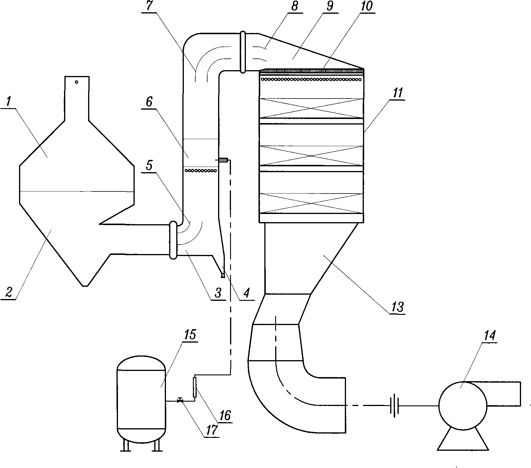
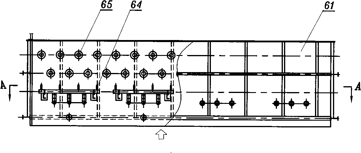
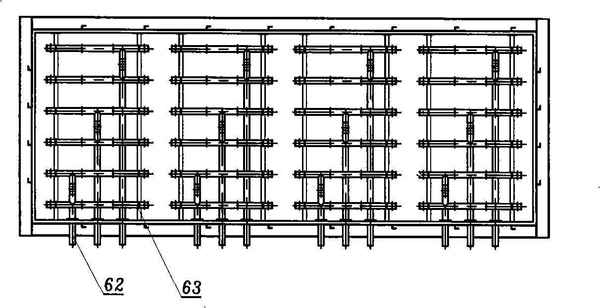
[0032] Such as Figure 1-3 As shown, the simulation platform of the flow field distribution structure of the denitrification device consists of an inlet pipe 1, an economizer 2, an inlet flue 3, an ash hopper 4, a gas injection device 6, a top flue 9, a flow equalizer 10, a reactor 11, Outlet flue 13, blower fan 14 are made up; Described gas injection device is made up of carbon monoxide gas distribution tank 15, shut-off valve 17, flowmeter 16, gas injection device housing 61, injection main pipe 62 that is installed on the housing 61, injection branch pipe 63, nozzle 64 and mixing tube 65 form. The outlet of the carbon monoxide gas distribution tank 15 is connected with the inlet of the injection main pipe 62 through a pipeline, and a shut-off valve 17 and a flow meter 16 are connected in series in the pipeline. The mixing pipe 65 is installed at the outlet of the nozzle 64, the outlet of the inlet pipe 1 is connected to the inlet of the economizer 2, the outlet of the econ...


PUM


Abstract

The invention discloses a simulating platform of the fume denitration device flow field distributing structure and a testing method. At present the denitration efficiency of the fume denitration device is greatly affected by the fume velocity distributing uniformity and the reducer ammonia gas/nitrogen oxide mixing uniformity. The invention includes an inlet pipe, a coal economizer, an inlet flue, a current stabilizing plate, a reactor, an outlet flue and a blower connected in turn, wherein an ash bucket is arranged at the round of the bottom of the inlet flue, and an air jetting device is arranged on the vertical section of the inlet flue. Guide plates located on the bottom of the top flue are arranged on the round of each flues. A plurality of layers of catalyzer are provided in the reactor, and a plurality of speed measuring holes are arranged at the entrance of the air jetting device and under the current stabilizing plate. The invention builds the simulating platform of the denitration device flow field structure, performs the experiment through the simulating platform, obtains the flow field distributing status of the denitration device, provides reasonable engineering measurement to improve the flow field distributing structure in the denitration system.

Description

technical field [0001] The invention relates to a simulation platform for the flow field distribution structure of an SCR (selective catalytic reduction) flue gas denitrification device suitable for thermal power plant boilers and a test method for testing the flow field distribution structure using the platform. Background technique [0002] The boiler SCR flue gas denitrification device of a thermal power plant has the function of removing the pollutant nitrogen oxides (NOx) in the flue gas, so as to meet the emission standards of the pollutants in the flue gas of the power plant. However, since the denitrification efficiency of the flue gas denitrification device is greatly affected by the uniformity of the flue gas flow velocity distribution and the mixing uniformity of the reducing agent ammonia gas / nitrogen oxides, if the flow velocity distribution is uneven or the mixing of ammonia gas / nitrogen oxides is uneven, the It will greatly reduce the denitrification efficienc...

Claims


Application Information

Patent Timeline
Patent Type & Authority Applications(China)
IPC IPC(8): G09B25/02
Inventor 曾永健徐芙蓉
Owner 浙江融智能源科技有限公司
Why Eureka
Try Eureka