Large multi-sensor integration electric claw
A multi-sensing, integrated electrical technology, applied in the directions of manipulators, chucks, manufacturing tools, etc., can solve the problem of not indicating the installation space and installation status, number, short, only to grab special objects such as I-beam, etc. Obtain the absolute position information of the finger and other issues, and achieve the effect of high integration of the mechanism and sensing system, compact structure and high opening and closing speed
- Summary
- Abstract
- Description
- Claims
- Application Information
AI Technical Summary
Problems solved by technology
Method used
Image

Examples
Embodiment Construction
[0016] Embodiments of the present invention are described in detail below in conjunction with accompanying drawings: the present embodiment is implemented under the premise of the technical solution of the present invention, and detailed implementation methods and specific operating procedures are provided, but the scope of protection of the present invention is not limited to Examples described below.
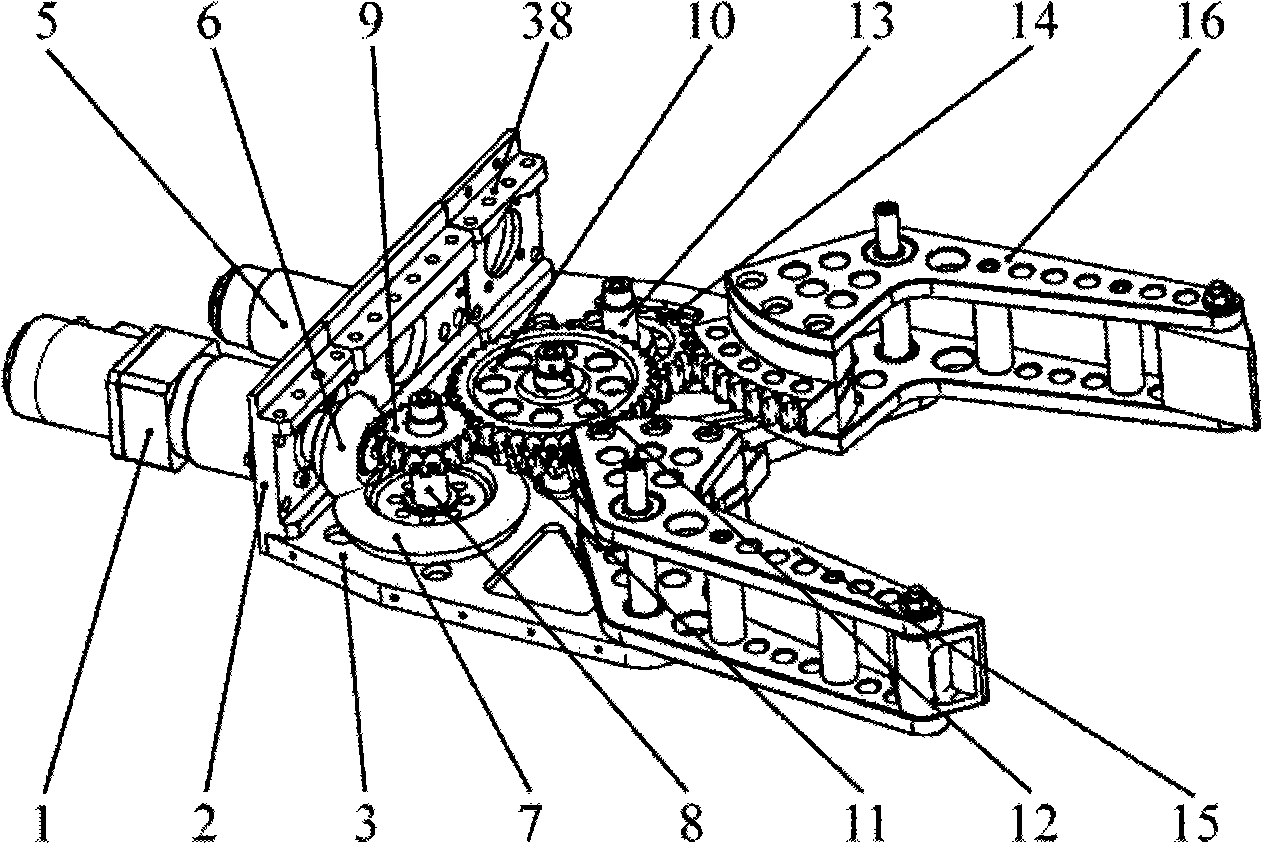
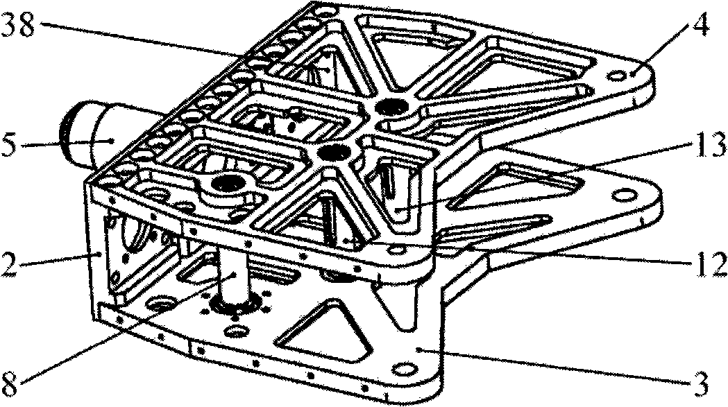
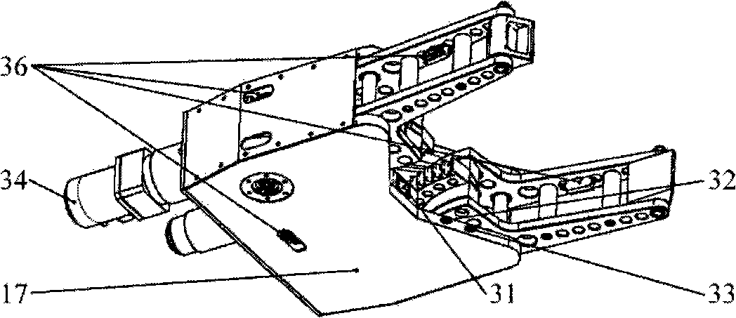
[0017] Such as figure 1 , figure 2 and image 3 As shown, this embodiment includes: geared motor 1, motor bracket 2, lower plate 3, upper plate 4, connector 5, small bevel gear 6, large bevel gear 7, pinion gear 9, large gear 10, the first counter-rotating Gear 11, second counter-rotating gear 14, first gear shaft 8, second gear shaft 12, third gear shaft 13, right finger assembly 15, left finger assembly 16, outer cover 17, multi-sensor system 18.
[0018] The interconnection relationship of each part is as follows: the lower plate 3, the upper plate 4, the motor bracket ...
PUM
 Abstract
Description
Claims
Application Information
PatSnap Eureka turns technology decisions into work you can execute. Powered by our Innovation Knowledge Graph, it runs expert workflows across engineering, life sciences, materials and intellectual property. Get your review-ready output in minutes.


