
Method for recognizing multiple touch point at infrared touch screen

An infrared touch screen and touch point technology, applied in the input/output process of data processing, instruments, electrical digital data processing, etc., can solve the problems of long scanning time, increased product cost, anti-light interference, etc., and achieve low application cost, Easy-to-produce, high-sensitivity effects

Active Publication Date: 2008-10-15
GENERALTOUCH TECH
View PDF2 Cites 32 Cited by
  • Summary
  • Abstract
  • Description
  • Claims
  • Application Information

AI Technical Summary

Problems solved by technology

[0006] According to its invention description and illustrations, 1. It is impossible to form Y=X[sinα*sin(α+β)] / sinβ in the partial area of ​​the four corners, and it will not be able to effectively identify in this area multi-touch
2. Because it adopts the method of sending and receiving twice, it will generate too much light interference, and the processing method it will adopt will also prolong the touch response time of the touch screen due to the response time characteristics of the infrared receiving tube
3. Because of the method of sending once and receiving twice, the realization of the circuit on the hardware will increase the product cost, and the logical realization also requires hardware support
4. Considering the anti-light interference at the edge, it will use infrared emitting and receiving tubes with different wavelengths on the X-axis and Y-axis, which will generate production and management costs
[0008] According to the description of its invention, under the same structural environment, the scanning time will be 5 times or more than that of a single point, and the scanning time will be too long. At this time, the touch response time of the touch screen will be greatly prolonged, which will affect the key technical parameters of the touch screen; in addition, Because the angle of the function matrix is ​​small, it will affect the adjacent multi-point detection

Method used


Image

  • Method for recognizing multiple touch point at infrared touch screen
  • Method for recognizing multiple touch point at infrared touch screen

Examples


Embodiment Construction

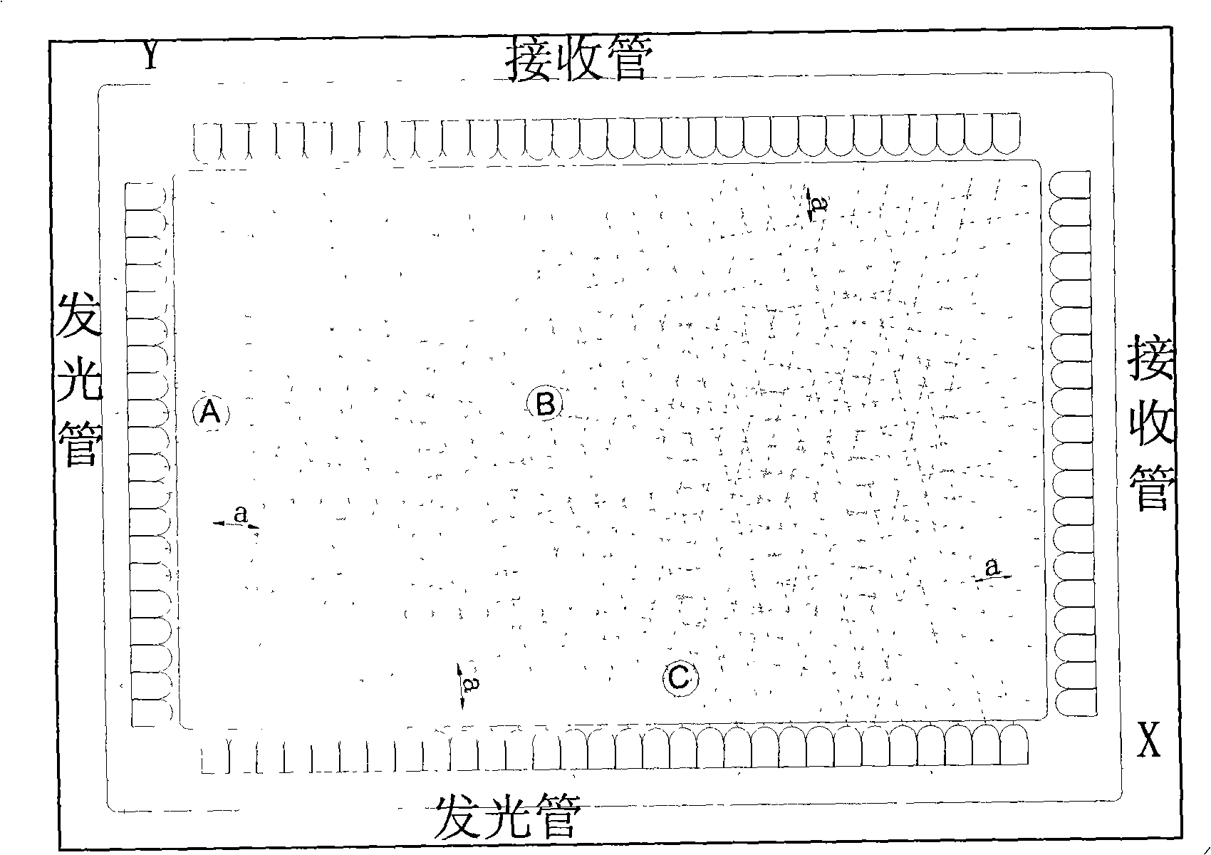
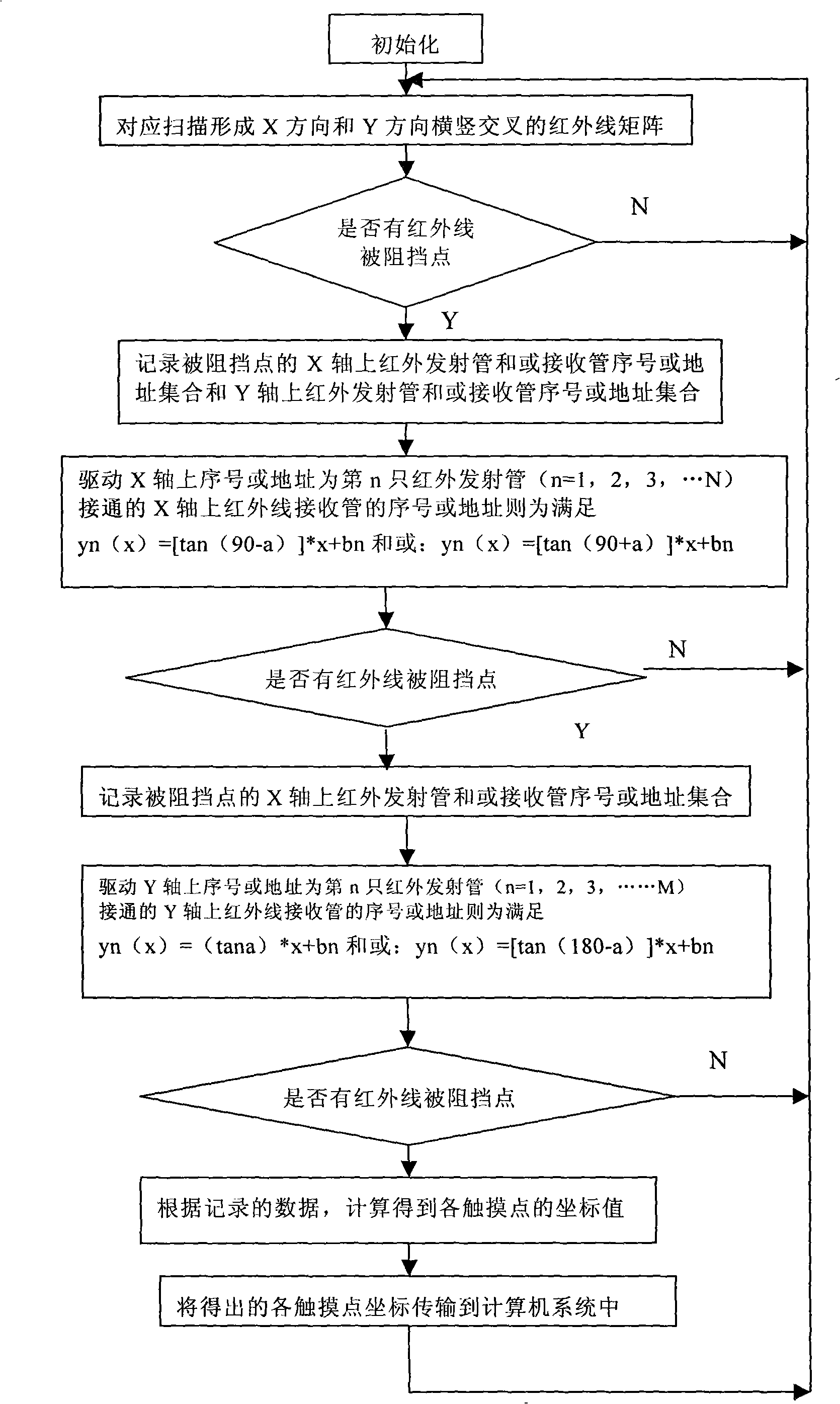
[0025]A method for identifying multiple touch points on an infrared touch screen, comprising the following steps: a. Start the infrared touch screen, drive the infrared emitting tube and the infrared receiving tube, scan correspondingly to form a horizontal and vertical infrared array, and record all touches when there is a touch Point on the infrared emission tube and or receiving tube serial number or address set on the X axis and the infrared emitting tube and or receiving tube serial number or address set on the Y axis; b, drive the infrared emitting tube and the infrared receiving tube, and the corresponding scanning is formed in the touch area to meet yn(x)=[tan(90-a)]*x+bn and / or: yn(x)=[tan(90+a)]*x+bn function relation infrared array and yn(x)=(tana )*x+bn and / or: yn(x)=[tan(180-a)]*x+bn function relation infrared ray array, record the infrared emitting tube and or receiving tube on the X axis of the blocked point when there is a touch The serial number or address set...


PUM


Abstract

The invention discloses a method for recognizing a plurality of touch points on an infrared touch screen, comprising the steps of: starting the infrared touch screen, driving an infrared emitter and an infrared receiver and forming transverse and longitudinal infrared arrays by corresponding scan; determining the transverse coordinates sets and longitudinal coordinates sets of all touch points, driving the infrared emitter and the infrared receiver, forming an infrared array with the functional relation of that y(x) is equal to f(x) in the touch area by corresponding scan, gaining a set of function value that y(x) is equal to f(x) of the touch points in the touch area, through calculating the sets of two scans by a controller, gaining the coordinates of all touch points and disposing and removing false touch points. The invention can complete the detection of a plurality of touch points without changing the hardware structure of existing touch screen, has no incorrect area of multi-point detection at four corners of the screen body, has higher sensitiveness to adjacent multi-point detection, higher resolution, short scan time and quick response.

Description

technical field [0001] The invention relates to a method for detecting touch points on an infrared touch screen, in particular to a method for identifying multiple touch points on an infrared touch screen. Background technique [0002] As a branch of computer touch screen, infrared touch screen is gradually widely used in various fields due to its advantages of convenient installation, maintenance-free, high explosion resistance, and high reliability. The basic structure of the infrared touch screen is to install several pairs of infrared emitting and infrared receiving elements in a certain order around the edge of a display surface suitable for installation. The angular displacement β of the infrared emitting tube and the receiving tube is generally less than or equal to ± ± when the relative radiation intensity is 0.5 times 15 degrees, these transmitting and infrared receiving elements form a transmitting and receiving pair in a one-to-one correspondence, forming a mutual...

Claims


Application Information

Patent Timeline
IPC IPC(8): G06F3/042
Inventor 沈海洋蒲彩林李想周辉石峰陈世洪吴康唐青
Owner GENERALTOUCH TECH
Learn More