Knee-joint prosthesis implantation process, osteotomy module thereof and device thereof

A knee joint prosthesis, knee joint technology, applied in joint implants, joint implants, knee joints and other directions, can solve problems such as prolonging operation time, increasing the risk of complications and errors in patients, and achieving extended operation. effect of time

Inactive Publication Date: 2008-10-22
周一新 +2
View PDF0 Cites 80 Cited by
  • Summary
  • Abstract
  • Description
  • Claims
  • Application Information

AI Technical Summary

Problems solved by technology
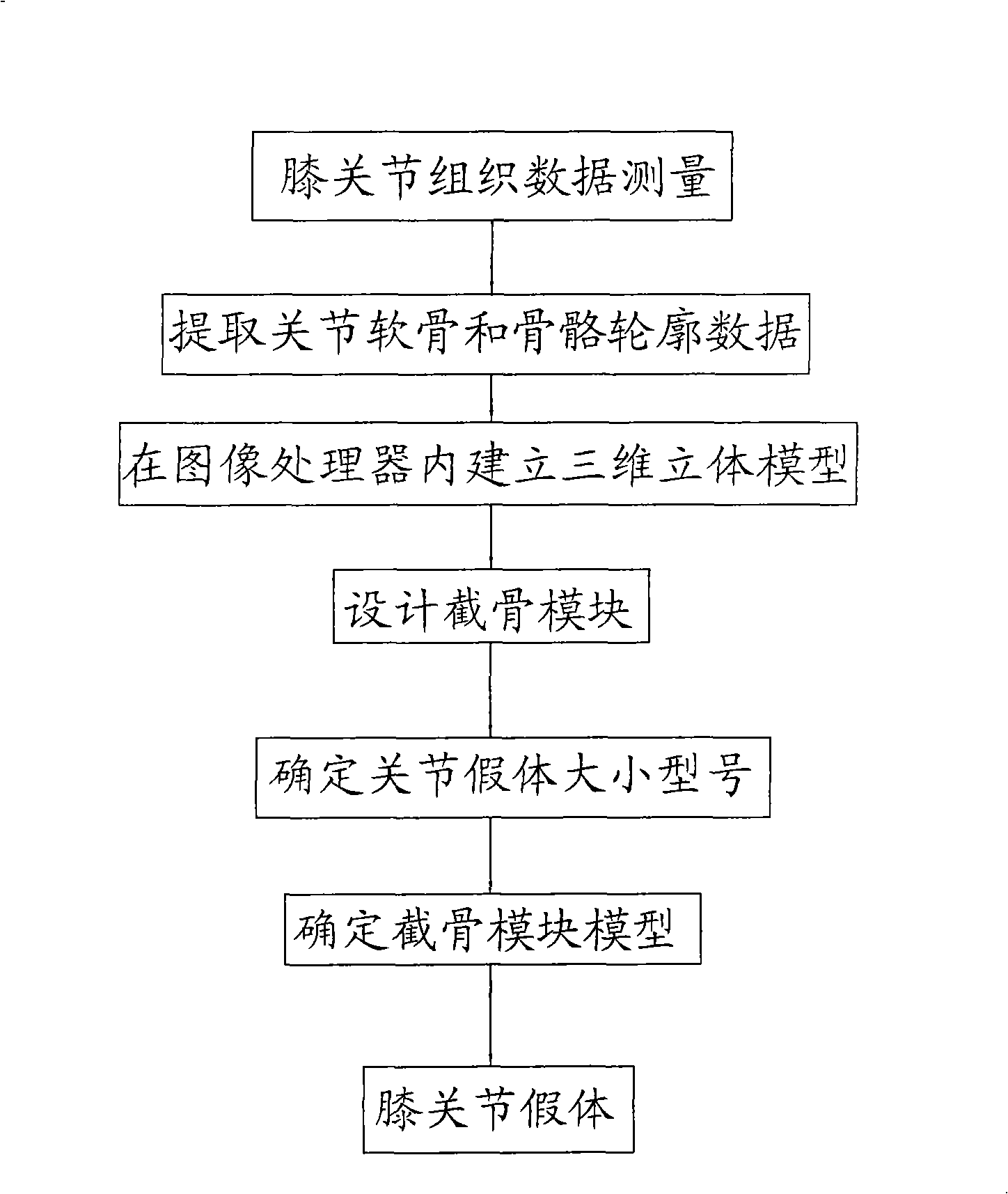
Although theoretically it can increase the accuracy of prosthesis placement, this method does not take into account the individual differences of patients, and the current knee joint registration system and positioning method are still being improved, so there are still certain errors, and many literature reports use Surgical navigation system for artifi

Method used


Image

  • Knee-joint prosthesis implantation process, osteotomy module thereof and device thereof
  • Knee-joint prosthesis implantation process, osteotomy module thereof and device thereof
  • Knee-joint prosthesis implantation process, osteotomy module thereof and device thereof

Examples


Embodiment 1

[0055] Example 1: For patients with varus deformity, please refer to Figure 5 , There is varus deformity in the tibia and femur, the femoral angle is 86°, and there is 2° varus. The tibial angle is 95° with 2° varus present. The measurement data of the femur are as follows: the anteroposterior diameter of the tibia is 6.13cm. The front face is 0.9cm thick. Genesis II5 prosthesis was selected. The femoral osteotomy block with perfect image preparation was designed for slotting. The groove at the distal end of the femur forms an angle of 84° with the mechanical axis of the femur, and an angle of 2° with the articular surface. Due to the presence of varus, the distance between the osteotomy groove and the distal end of the outer side is relatively large. Parallel to the line connecting the posterior condyle osteotomy groove and the posterior condyle, the distance from the anterior face osteotomy groove to the distal end is 9mm, the posterior condyle osteotomy distance is 9.3...

Embodiment 2

[0056] Embodiment 2: Valgus deformity patient, please refer to Figure 6According to the preoperative CT, MRI and X-ray measurements, both the femur and the tibia had valgus deformities. The femoral angle was 80°, with 4° valgus, and the tibial angle was 90°, with 3° valgus deformity. The anteroposterior diameter of the femur is 5.45cm, and the anterior face thickness is 0.6cm. The Genesis II No. 2 prosthesis is used, and the corresponding slot design is carried out. The groove at the distal end of the femur forms an angle of 84° with the mechanical axis of the femur, an angle of 4° with the articular surface, and is 10mm away from the most distal end of the articular surface. The groove of the posterior condyle of the femur is parallel to the line of the posterior condyle, the distance from the most distal end of the posterior condyle osteotomy is 13.5mm, and the bone volume of the anteroposterior diameter is 35mm (to ensure that it is suitable for the No. 5 Genesis II prosth...


PUM

PropertyMeasurementUnit
Thicknessaaaaaaaaaa

Abstract

The invention discloses a knee prosthesis implantation method, an osteotomy module for usage and a using device, the knee prosthesis implantation method comprises the following steps of measuring the data of knee joint bone tissues, extracting the data of articular cartilage and the skeleton profile, establishing a three-dimensional model in an image processor, designing the osteotomy module, determining the size and the type of the used knee prosthesis and determining an osteotomy module model and the implantation of the knee prosthesis. The knee prosthesis implantation method of the invention can reduce the trauma of a patient, lower the cost, shorten the implantation time, reduce the risk of complications of a user of the knee prosthesis and have comparatively small error and higher precision.

Description

technical field [0001] The present invention relates to a method for implanting a knee joint prosthesis, and also relates to an osteotomy module used in the aforementioned method for implanting a knee joint prosthesis, and also relates to a device used in the aforementioned method for implanting a knee joint prosthesis. Background technique [0002] At present, when people's knee joints are worn or broken, more and more people choose to install artificial knee joints to replace the original knee joints. How to implant the knee prosthesis more accurately in artificial knee replacement surgery is very important for the postoperative function and prognosis of patients. At present, the implantation of knee joint prosthesis mainly relies on the following two methods: one method is to use intramedullary and extramedullary positioning instruments during operation: when using this method, intramedullary positioning is generally used on the femoral side, and the intramedullary positi...

Claims


Application Information

Patent Timeline
IPC IPC(8): A61B17/56A61F2/38A61F2/46
Inventor 邵宏翊唐竞唐杞衡周一新
Owner 周一新
Why Eureka
Try Eureka