Optimizing hydrogenation and heat-exchange system

A technology of heat exchange system and hydrogenation reaction, applied in the field of heat exchange system, can solve the problems of high resource consumption, no energy saving, high energy consumption of the device, and achieve the effects of optimizing heat exchange network, reducing oil refining cost and saving heat source steam.

Active Publication Date: 2012-08-29
SHANGHAI YOUHUA PROCESS INTEGRATED TECH CO LTD
View PDF2 Cites 2 Cited by
  • Summary
  • Abstract
  • Description
  • Claims
  • Application Information

AI Technical Summary

Problems solved by technology

[0002] At present, the heat exchange network of the known hydrogenation unit is characterized by cold feed and cold discharge. The flow between the upstream and downstream unit devices first cools down and then heats up, and the heat exchange between the flows also has high temperature and low utilization. The multi-level utilization of high-temperature potential heat has not been realized, resulting in energy waste, which is not in line with the scientific energy use principle of "corresponding temperature, cascade utilization", resulting in large fuel and steam consumption and cold utility consumption, high energy consumption of the device, and resource consumption Many, the specific process is as follows:
[0003] The raw oil at about 60-250°C passes through the air cooler 11 and water cooler 12 in the upstream device 1, and is cooled to a normal temperature of 50°C as the raw material for the hydrogenation unit 6; the raw material for the hydrogenation unit 6 at a normal temperature of 50°C and The hydrogenation reaction product coming out from the bottom of the hydrogenation reactor 7 is heat exchanged to T 1 Backward heating furnace 5 is heated to required reaction temperature T r , and then enter the hydrogenation reactor 7 as a feed; since the hydrogenation unit 6 is a cold feed at a normal temperature of 50°C, the heat exchange temperature difference between the normal temperature feed and the very high temperature hydrogenation reaction product is large, so that the high temperature of the hydrogenation product Potential heat has not been scientifically, rationally and fully utilized, and T r with T 1 The temperature difference of the heating furnace 5 is relatively large, so that the amount of primary energy fuel consumed by the heating furnace 5 is relatively large, which is not energy-saving;
[0004] In addition, the hydrogenation reaction product with a temperature of Tp from the hydrogenation reactor 7 exchanges heat with the 50° C. cold feed of the hydrogenation unit 6 to Tp 2 , into the air cooler 21 and water cooler 22 to cool down to T 3 , the intake-liquid separation tank 10 carries out gas-liquid separation; the temperature coming out from the gas-liquid separation tank 10 is T 3 The liquid phase product and the hydrogenation reaction product at the bottom of the hydrogenation product fractionating tower 8 are heat exchanged to T 4 Enter hydrogenation product fractionation column 8 as feed, here T 2 Cool directly to T 3 Part of the thermal energy caused by the hydrogenation product is not utilized;
[0005] Also, the temperature T 5 The hydrogenation reaction product at the bottom of the hydrogenation product fractionation tower 8 and the feed of the hydrogenation product fractionation tower 8 are heat exchanged to T by heat exchanger 41 6 , due to the cold feed to the hydrogenation unit 6, T 6 with T 5 The temperature difference between them is large, so that the temperature is T 5 The heat of the hydrogenation reaction product at the bottom of the higher temperature position of the tower is not fully utilized; the temperature is T 6 The hydrogenation reaction product enters the air cooler 31 and the water cooler 32, is cooled to 60°C, and goes out of the device into the oil storage tank;
[0006] Due to the cold feeding of the above process, the following aspects are ultimately wasted: energy consumption and material consumption of cold utilities; high-quality primary energy and fuel consumption of the heating furnace

Method used


Image

  • Optimizing hydrogenation and heat-exchange system
  • Optimizing hydrogenation and heat-exchange system
  • Optimizing hydrogenation and heat-exchange system

Examples


Embodiment Construction

[0014] The present invention will be further described below, and the present invention is relatively clear to those skilled in the art.

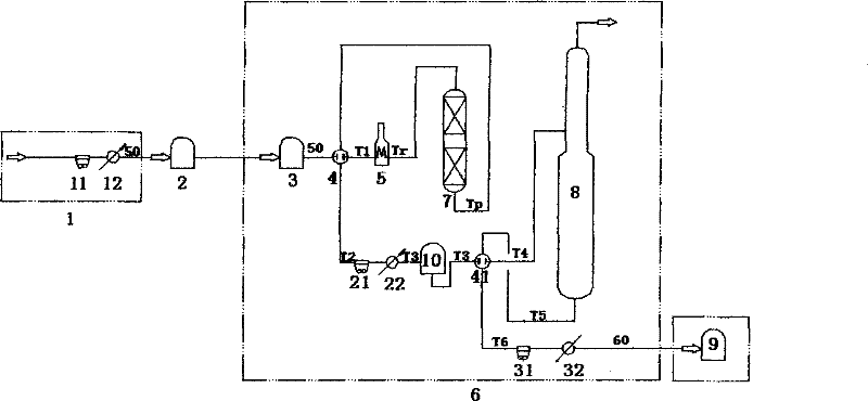
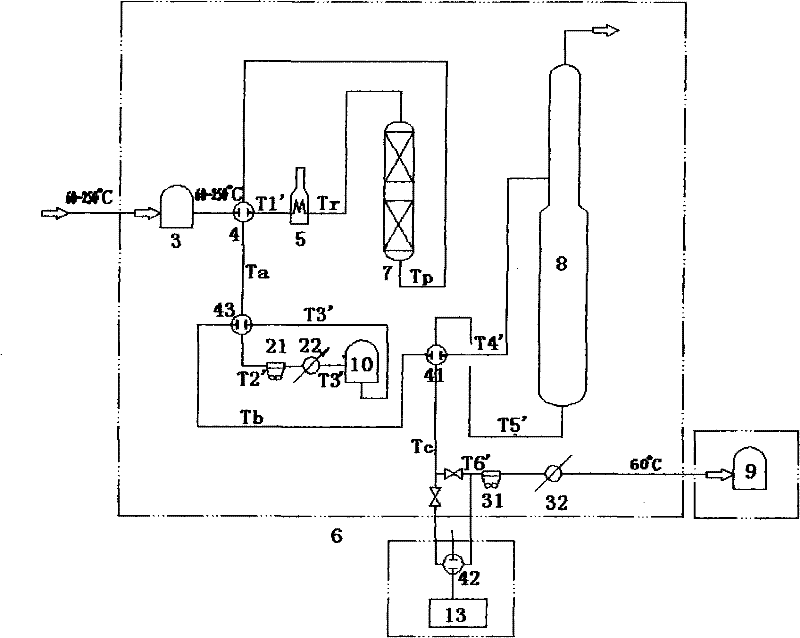
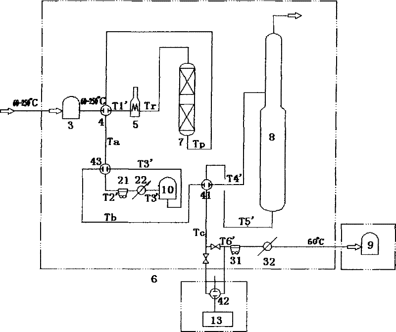
[0015] The device in this hydrogenation heat exchange system is a process device that reacts with hydrogen as the reaction raw material or in a hydrogen environment. The raw material oil at about 60-250 ° C is directly converted to 60 °C without cooling by the upstream device and the intermediate storage tank 2. The hot feed at around -250°C enters the raw oil buffer tank 3 of the hydrogenation unit 6, which strengthens the heat exchange between the feed and the pre-hydrogenation product, so that the final heat transfer temperature of the feed is changed from the original lower T 1 raised to T 1 ’, shrink T r with T 1 The temperature difference greatly reduces the load of the heating furnace 5, and finally saves the consumption of primary energy and fuel of the heating furnace 5;

[0016] The temperature out of the hydrogenation reactor ...


PUM


Abstract

The invention relates to a heat exchange system in a hydrogenation device, in particular to an optimized hydrogenation heat exchange system, which comprises a hydrogenation device (6), wherein 60 to 250 DEG C high-temperature base oil is fed in the hydrogenation device (6) to carry out hydrogenation reaction. The optimized hydrogenation heat exchange system is characterized in that the 60 to 250 DEG C high-temperature base oil is not cooled down; direct hot feed and the hydrogenation reaction product discharged from the bottom of a hydrogenation reactor (7) reach to a temperature T1' through heat exchange, thereby reducing the energy consumed by a heating furnace (5) when heated to Tr. Compared with the prior art, the optimized heat exchange network of the invention saves fuel gas and the heat source steam of a tower bottom reboiler, and reduces device energy consumption and oil refining cost so as to increase economic benefit.

Description

[technical field] [0001] The invention relates to a heat exchange system in a hydrogenation unit, in particular to an optimized hydrogenation heat exchange system. [technical background] [0002] At present, the heat exchange network of the known hydrogenation unit is characterized by cold feed and cold discharge. The flow between the upstream and downstream unit devices first cools down and then heats up, and the heat exchange between the flows also has high temperature and low utilization. The multi-level utilization of high-temperature potential heat has not been realized, resulting in energy waste, which is not in line with the scientific energy use principle of "corresponding temperature, cascade utilization", resulting in large fuel and steam consumption and cold utility consumption, high energy consumption of the device, and resource consumption Many, the specific process is as follows: [0003] The raw oil at about 60-250°C passes through the air cooler 11 and water...

Claims


Application Information

Patent Timeline
Patent Type & Authority Patents(China)
IPC IPC(8): C10G45/00C10G49/00F28D7/00
Inventor 张高博黄鸯珍
Owner SHANGHAI YOUHUA PROCESS INTEGRATED TECH CO LTD
Why Eureka
Try Eureka