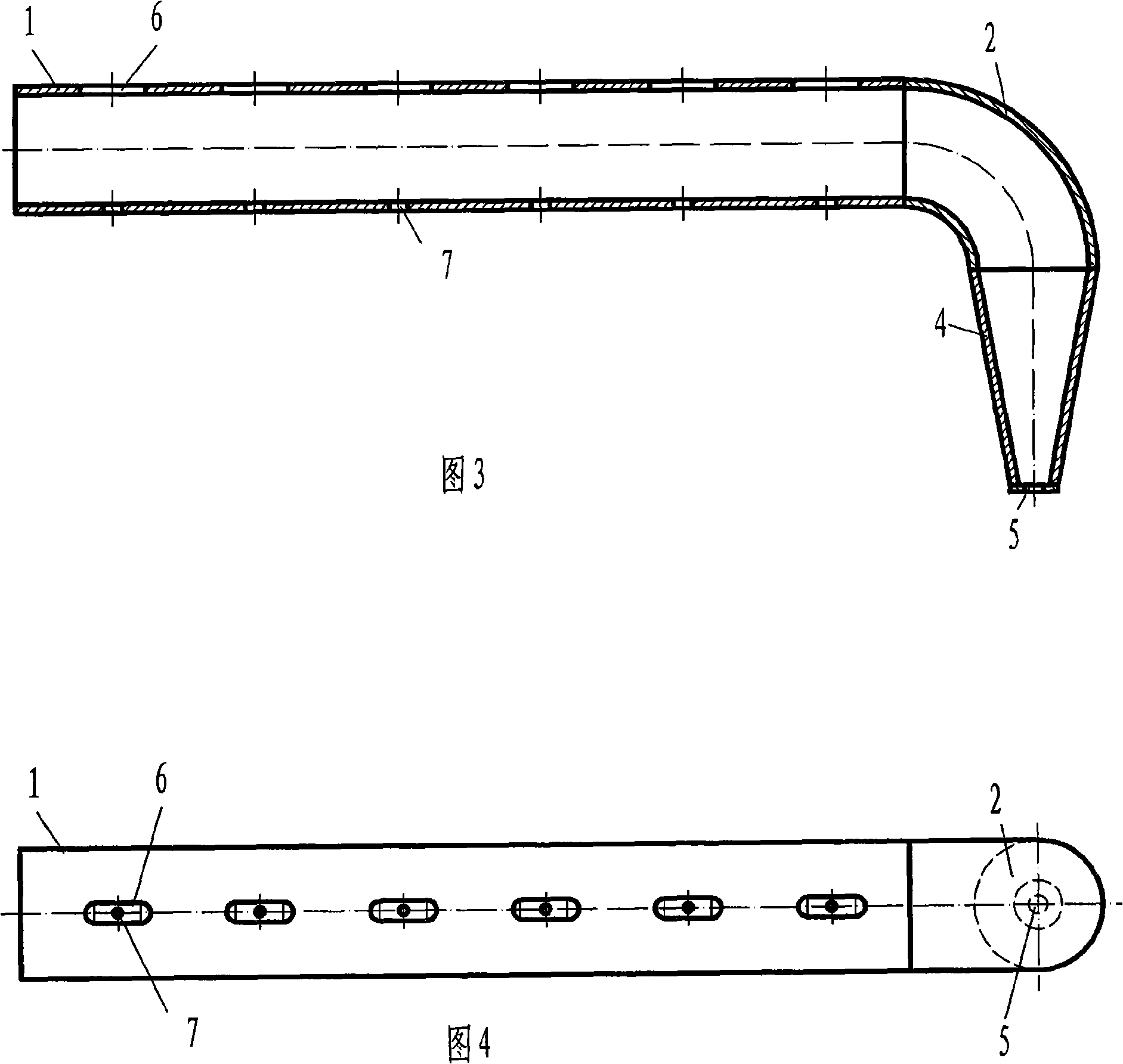
Multi-jet spray pulse conduit pipe
A multi-nozzle and duct technology, which is applied in the treatment of combustion products, combustion methods, and removal of solid residues, etc., can solve the problems of erosion and wear of the heating surface, threats to the safety of the heating surface and flue, and easy damage to the heating surface.
Inactive Publication Date: 2008-10-22
BEIJING GAOZHAN SCI & TECH
View PDF0 Cites 3 Cited by
- Summary
- Abstract
- Description
- Claims
- Application Information
AI Technical Summary
Problems solved by technology
1. Fly ash powder falling from above the pulse conduit falls into the nozzle from the upward nozzle to form dry loose ash deposits, which can be sprayed to the heating surface at high speed along with the pulse jet generated by the explosion when the pulse soot blower performs soot blowing operations , causing strong erosion and wear to the heating surface, which will easily damage the heating surface over time, and even induce safety accidents such as "pipe burst";
2. Not only fly ash powder falls into the pulse conduit from the spout, but sometimes coke fragments, hardened ash fragments, refractory material fragments falling from the furnace wall, etc., these fragments can also be in the pulse When the soot blower performs the soot blowing operation, it is ejected at high speed with the pulse jet generated by the explosion, just like the "gun sand" ejected by the earth gun, which poses a serious threat to the safety of the heating surface and the flue
Method used
View moreImage
Smart ImageViewing Examples
Examples
Embodiment 1
Embodiment 2
Login to View More PUM
 Abstract
The invention belongs to the thermal explosion pulse sootblowing technical field, and in particular relates to a multi-nozzle pulse conduit of a thermal explosion pulse sootblower, mainly comprising the multi-nozzle pulse conduit with an upward tail end connected with an elbow in 90 degrees, wherein, an end enclosure or a concentric reducer is connected under the elbow, and an ash discharging port is arranged on the bottom of the end enclosure or on the nethermost part of the concentric reducer. The multi-nozzle pulse conduit has the advantages that the multi-nozzle pulse conduit of the thermal explosion pulse sootblower provides a proposal with extreme high security under the circumstance that the nozzles are upward, well protects a heating surface to which the nozzles face, and greatly improves the application security of the thermal explosion pulse sootblower.
Description
A multi-jet pulse catheter technical field The invention belongs to the technical field of thermal explosion pulse soot blowing, and in particular relates to a multi-nozzle pulse conduit of a thermal explosion pulse soot blower. Background technique Thermal explosion pulse sootblower is referred to as pulse sootblower, also known as shock wave sootblower, shock wave sootblower, weak explosion sootblower, detonation wave sootblower, detonation wave sootblower, detonation pulse sootblower, etc. , was first invented by the former Soviet Union and introduced to my country in 1988. It evolved from the "gas cannon". Internal ignition explosion, using the "alternating stamping and suction effect" of the compression shock wave generated by the explosion, the "physical micro-explosion effect" and the "purge effect" of the high-speed pulse jet to blow off various accumulations on the heating surface of the boiler and the wall of the flue. At the same time, it has three cleaning effect...
Claims
Login to View More Application Information
Patent Timeline
 IPC IPC(8): F23J1/00F23J3/00
Inventor 曹义国
Owner BEIJING GAOZHAN SCI & TECH
Features
- R&D
- Intellectual Property
- Life Sciences
- Materials
- Tech Scout
- Unparalleled Data Quality
- Higher Quality Content
- 60% Fewer Hallucinations
Learn More Browse by: Latest US Patents, China's latest patents, Technical Efficacy Thesaurus, Application Domain, Technology Topic, Popular Technical Reports.
© 2025 PatSnap. All rights reserved.Legal|Privacy policy|Modern Slavery Act Transparency Statement|Sitemap|About US| Contact US: help@patsnap.com


