Matching method for coaxial laser converting to butterfly shape laser

A coaxial laser and matching method technology, which is applied in the coupling of optical waveguides, electromagnetic transmitters, electromagnetic wave transmission systems, etc., can solve the problems that coaxial lasers cannot be used universally with butterfly lasers, and achieve the effect of improving modulation efficiency

Inactive Publication Date: 2011-05-25
BEIJING BUPT GUOAN TECH
View PDF0 Cites 0 Cited by
  • Summary
  • Abstract
  • Description
  • Claims
  • Application Information

AI Technical Summary

Problems solved by technology

[0003] The purpose of the present invention is to provide a matching method from a coaxial laser to a butterfly laser to solve the problem that the coaxial laser cannot be used in common with the butterfly laser

Method used


Image

  • Matching method for coaxial laser converting to butterfly shape laser
  • Matching method for coaxial laser converting to butterfly shape laser
  • Matching method for coaxial laser converting to butterfly shape laser

Examples


Embodiment Construction

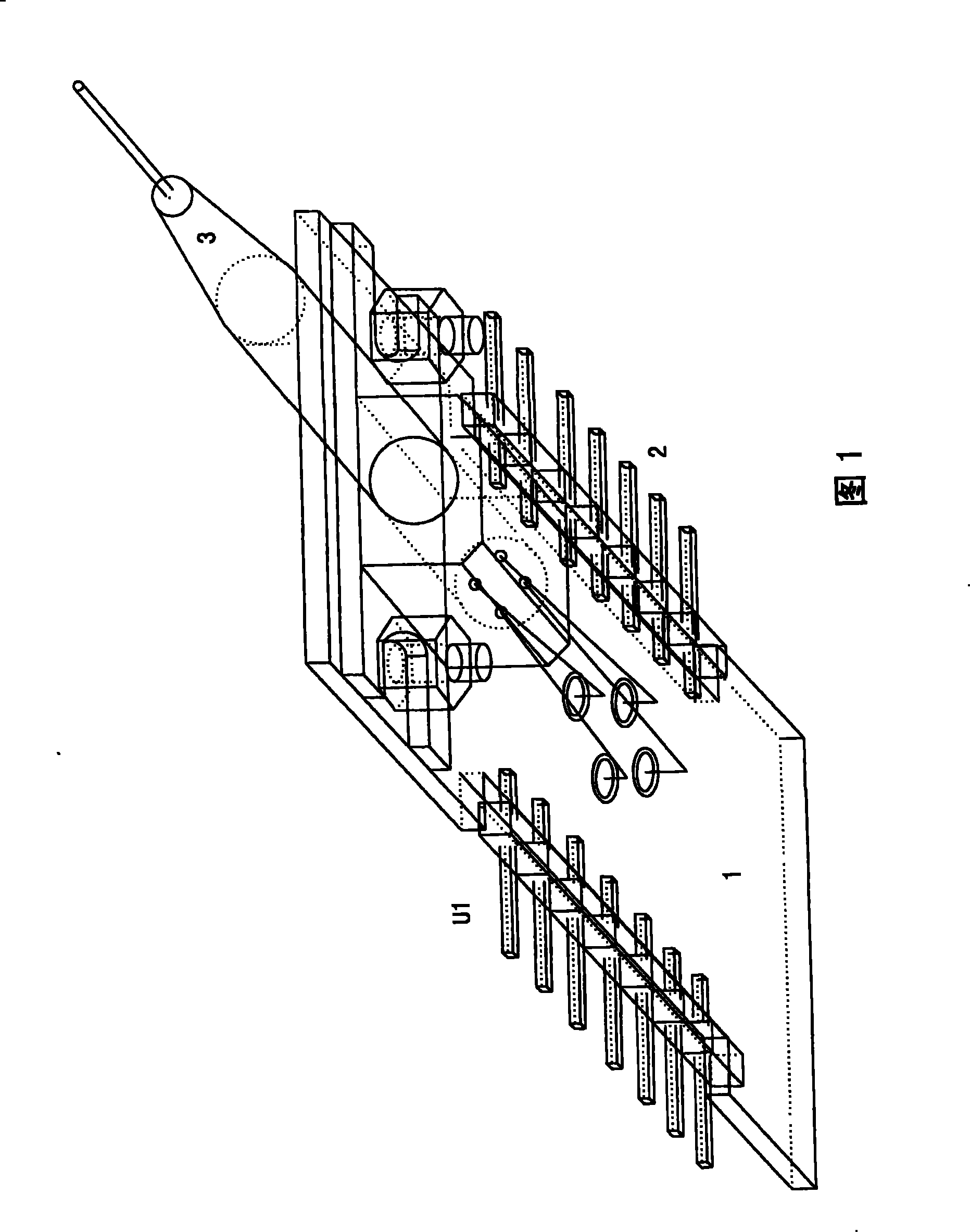
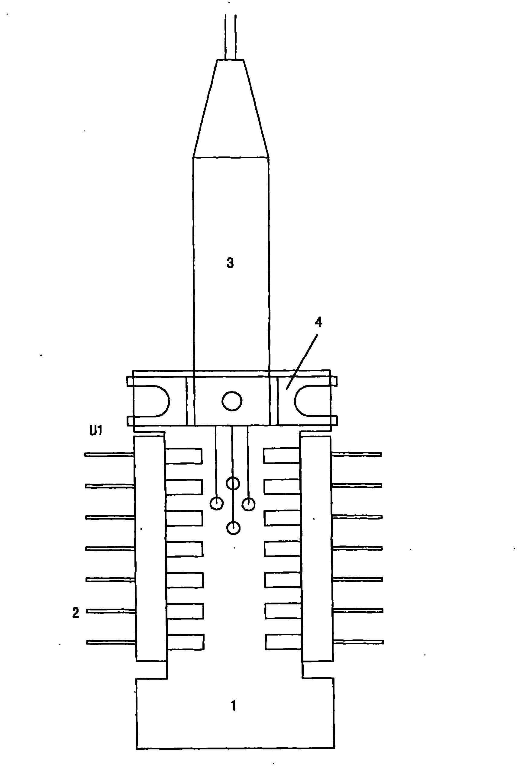
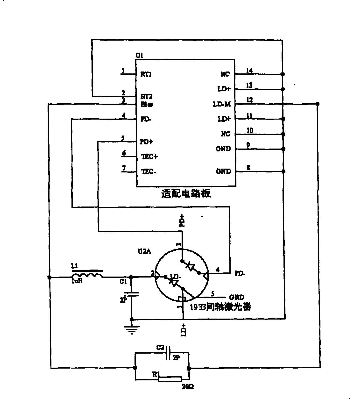
[0020] The technical solution of the needle of the present invention is to complete the matching packaging of the axial laser and the butterfly laser through the appearance of the adapter board circuit, and to carry out the matching of the electrical connection according to the pin definition of the butterfly laser. To match the appearance of the laser package, it is first necessary to design the overall appearance, size and soldering pin specifications of the coaxial laser to be consistent with the butterfly laser. Solder the coaxial laser on the adapter circuit board first, and then weld it on the circuit board of the original butterfly laser transmitter.

[0021] This example takes the 1688 butterfly laser and the 1933 coaxial laser produced by Anke Company of the United States as examples to illustrate.

[0022] see figure 1 and figure 2 , according to the appearance size of the butterfly laser, the peripheral size of the adapter circuit board 1 is 16*28mm, and it is in...


PUM


Abstract

The invention relates to a matching method for a coaxial laser and a butterfly laser. The method is to fix the coaxial laser on an adaptation circuit board, which is welded on a laser slot of a circuit board of an optical transmitter in the butterfly laser, a plurality of pitch headers on both sides of the adaptation circuit board are connected to the circuit board of the optical transmitter; theanode of a laser diode of the coaxial laser is connected to the ground, the cathode of the laser diode of the coaxial laser is connected to a laser bias current pin which is connected to the adaptation circuit board through filter inductance; the anode of a backlight diode of the coaxial laser is connected to an anode pin of the backlight diode of the adaptation circuit board; the cathode of the backlight diode of the coaxial laser is connected to a cathode pin of the backlight diode of the adaptation circuit board; the cathode of the laser diode of the coaxial laser is connected to the ground through a capacitor; a matched resistance is arranged between a radio-frequency signal pin of the adaptation circuit board and the cathode pin of the laser diode of the adaptation circuit board in series, the resistance value of the matched resistance is equal to that of an internal isolation resistance of the butterfly laser.

Description

technical field [0001] The invention relates to a cable television optical transmission method, in particular to a matching method of a coaxial laser and a butterfly laser. Background technique [0002] Optical transmitters in the field of cable TV optical transmission have long used butterfly-shaped packaged DFB lasers (distributed feedback semiconductor lasers). DFB lasers have the advantages of high index transmission and long distance, so they have been widely used in CATV optical transmitters. applications, hundreds of thousands of such lasers are currently in use on the market. Butterfly-packaged laser processing technology is difficult and costly. With the increasingly fierce market competition and technological development, the market gradually begins to introduce low-cost coaxial packaged DFB lasers, which can directly replace lasers in terms of performance. The original butterfly package DFB laser, but due to the huge difference in structure and slightly different...

Claims


Application Information

Patent Timeline
IPC IPC(8): G02B6/42H04B10/04H04B10/50
Inventor 邵宁莫世君
Owner BEIJING BUPT GUOAN TECH
Why Eureka
Try Eureka