
Bit-shifting register device and bit-shifting register

A shift register and low-potential technology, applied in static memory, digital memory information, instruments, etc., to achieve the effect of reducing manufacturing cost and reducing circuit size

Active Publication Date: 2008-10-22
HANNSTAR DISPLAY CORPORATION
View PDF0 Cites 5 Cited by
  • Summary
  • Abstract
  • Description
  • Claims
  • Application Information

AI Technical Summary

Problems solved by technology

Therefore, although this shift register device only needs to provide N output signals, it needs N+1 shift registers to operate

Method used


Image

  • Bit-shifting register device and bit-shifting register
  • Bit-shifting register device and bit-shifting register
  • Bit-shifting register device and bit-shifting register

Examples


Embodiment Construction

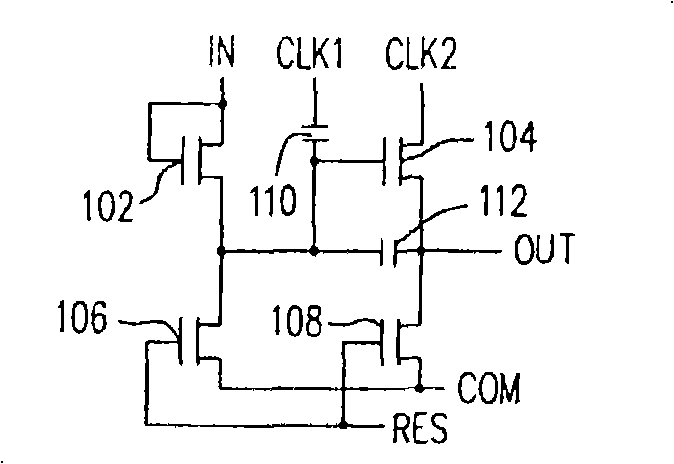
[0030] image 3 This is the shift register of the first embodiment of the present invention. The shift register includes an input unit 311, a feedback unit 312, a reset unit 313, and an output unit 314. In this embodiment, each unit is composed of at least one switch. For example, the input unit 311 includes a switch 301, the feedback unit 312 includes a switch 302, the reset unit 313 includes switches 303 and 305, and the output unit 314 includes a switch 304. The switches 301 to 305 all have a first terminal, a second terminal, and a control terminal, and these switches all determine whether to turn on or not according to the signal received by the control terminal.

[0031] The first terminal of the switch 301 of the input unit 311 receives an input signal IN, and the control terminal thereof receives a clock signal CLK1 (ie, the first signal) to determine whether to conduct the input signal IN to the second terminal. The first terminal of the switch 304 of the output unit 314...


PUM


Abstract

The invention relates to a shift register device and a shift register of the same, wherein the shift register comprises an input unit, a feedback unit, an output unit and a reset unit. The shift register can make use of any switching element selected from MOS, BJT and other switching transistors to form a shift register circuit, and makes use of the special coupling relation of the units to collocate different clock signals during two pulse waves, thereby realizing the registering and the displacement of an input signal.

Description

Invention field [0001] The present invention relates to a driver device, and more particularly to a shift register device of a driver device and its shift register. technical background [0002] figure 1 It is the shift register architecture in the traditional driver device, which is generally known as the Thomson circuit. The shift register includes NMOS transistors (N type metal oxide semiconductor transistors) 102 to 108, and capacitors 110 and 112. IN, OUT, RES, and COM in the figure represent input signal, output signal, reset signal, and common potential, respectively, while CLK1 and CLK2 represent two different clock signals, respectively. [0003] The input signal IN is a pulse signal, and the pulse enable periods of the input signal IN and the clock signal CLK1 are the same, while the pulse enable periods of the clock signals CLK1 and CLK2 are different from each other. When the clock signal CLK1 is at a high potential and the clock signal CLK2 is at a low potential, t...

Claims


Application Information

Patent Timeline
IPC IPC(8): G11C19/00G09G3/36
Inventor 蓝根琪
Owner HANNSTAR DISPLAY CORPORATION
Features
  • Generate Ideas
  • Intellectual Property
  • Life Sciences
  • Materials
  • Tech Scout
  • Unparalleled Data Quality
  • Higher Quality Content
  • 60% Fewer Hallucinations
Learn More