Photovoltaic sensor tracing angle of light

A sensor and light angle technology, applied in the field of automatic sun tracking systems, can solve the problems of indistinguishable small differences, less sunlight irradiation, sensor output errors, etc., to achieve high performance and low price, enhance the ability to resist sand and dust, The effect of strong practicality

Inactive Publication Date: 2008-10-22
INST OF ELECTRICAL ENG CHINESE ACAD OF SCI +1
View PDF2 Cites 28 Cited by
  • Summary
  • Abstract
  • Description
  • Claims
  • Application Information

AI Technical Summary

Problems solved by technology

Chinese patent CN2636210Y "photocell sensor of solar automatic tracking system based on cassette projection method" proposes a method of using slits to generate narrow and long light to irradiate the photocell to distinguish the position of the sun. This method has simple ideas and low cost, but the sensor is photosensitive The range is small, when the sun deviates too much, the sunlight can only shine on the inner wall of the box after passing through the slit, and will not be able to shine on the photocells on the bottom surface of the box, so it is impossible to find the position of the sun
However, its ability to adapt to dust, snow and other environments is poor. When the filter is asymmetrically polluted, the output of the sensor will produce a fixed error. Even if the filter is not polluted, when the incident angle of sunlight is small , the two symmetrical photosensitive elements receive very little sunlight irradiation, and it is difficult for the built bridge comparison circuit to distinguish the small difference at this time, so it is difficult for this circuit to obtain high tracking accuracy

Method used


Image

  • Photovoltaic sensor tracing angle of light
  • Photovoltaic sensor tracing angle of light
  • Photovoltaic sensor tracing angle of light

Examples


Embodiment Construction

[0017] The present invention will be further described below in conjunction with the accompanying drawings and specific embodiments.

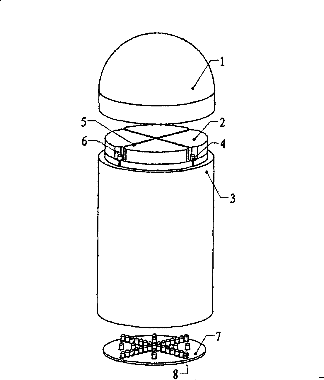
[0018] The photovoltaic tracking light angle sensor of the present invention is composed of two parts, namely a main part and a post-processing circuit. figure 1 with figure 2 its main part. Such as figure 1 As shown, the present invention includes a hemispherical transparent glass cover 1, a top flat baffle plate 2, a cylindrical side surface 3, a light-transmitting slit 5, a facade groove 6, and a bottom surface 7.

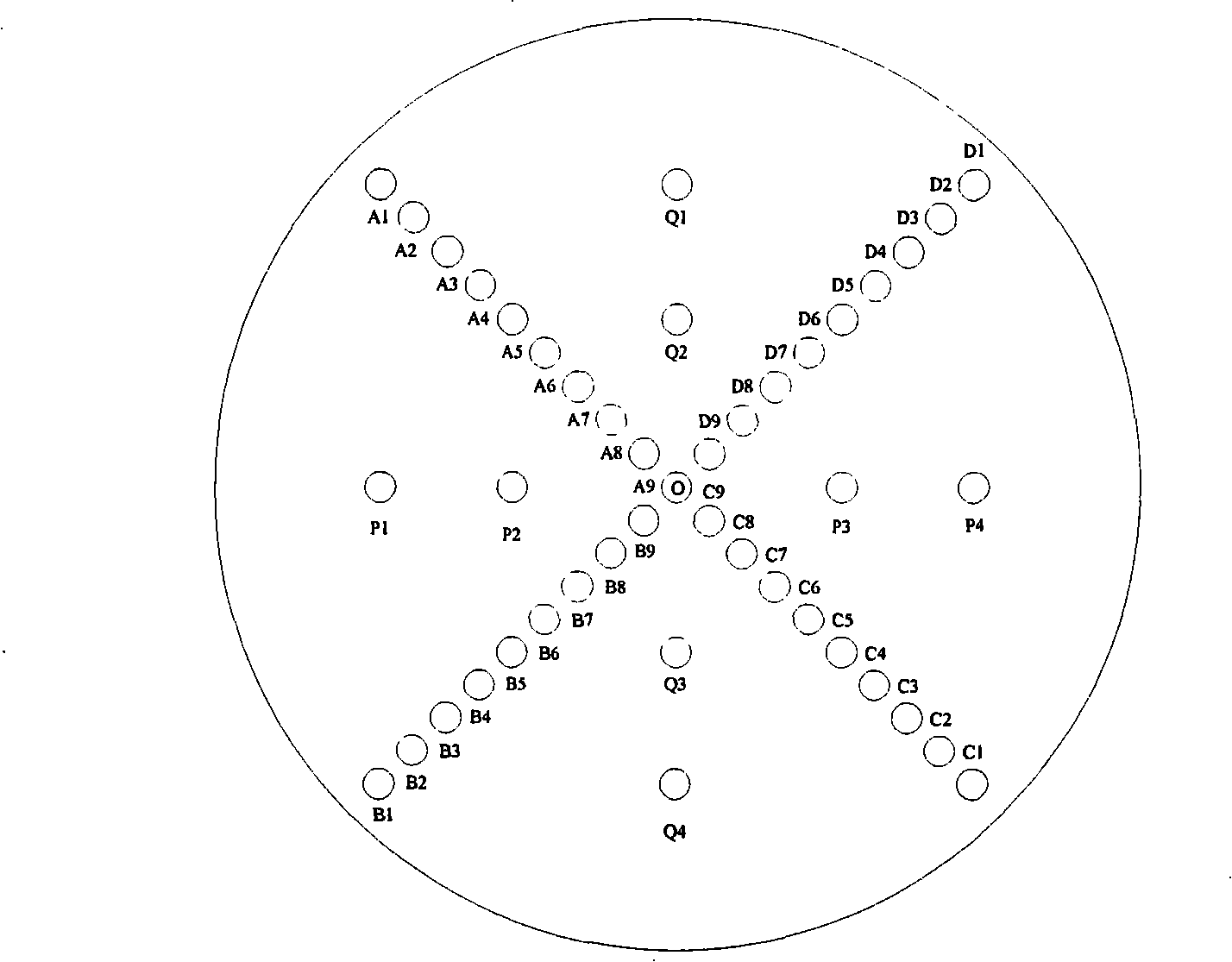
[0019] The hemispherical transparent glass cover 1 is covered on the cylindrical side 3 and closely combined with the cylindrical side 3 . The photosensitive element 4 is composed of four photosensitive diodes, which are symmetrically distributed in four directions of east, south, west and north. There are four facade grooves 6, corresponding to the four photodiodes, distributed symmetrically in the east, south, west, and no...


PUM


Abstract

The invention discloses a photovoltaic tracking optical angle sensor, consisting of a sensor body structure and a sensor post-stage signal processing circuit. The body structure part mainly comprises a sealing transparent glass shade 1, a top surface horizontal baffle 2, a sensor column side 3, photosensor elements 4, a light transmission slit 5, a facade groove 6 and a bottom surface photosensor element. The post-stage signal processing circuit mainly comprises a top surface photosensor element output signal processing circuit and a bottom surface photosensor element output signal processing circuit. The optical angle sensor adopts two working ways of coarse detection and precise detection. The coarse detection is finished by using four photosensor elements on the top surface which are arranged symmetrically and corresponding electric bridge comparison circuits, and the precise detection is finished by using the slit on the top surface, the photosensor element on the bottom surface and corresponding signal processing circuits. The photovoltaic tracking optical angle sensor can not only have higher tracking precision, but also have wider detection angle range, thereby well adapting to environment of wind-sand and having better capacity of resisting rain and snow.

Description

technical field [0001] The invention relates to an automatic sun tracking system, in particular to a photovoltaic tracking light angle sensor. Background technique [0002] With the increasingly prominent energy and environmental issues, the development and utilization of renewable energy has gradually attracted the attention of the world. Solar energy has become a fast-growing renewable energy due to its cleanness, wide distribution range, and convenient utilization. Solar photovoltaic power generation is one of the main forms of solar energy utilization, but due to the high price of solar panels, the cost of photovoltaic power generation remains high, thus restricting the development of solar photovoltaic power generation industry. Therefore, how to improve the utilization efficiency of solar energy and reduce the cost of solar energy utilization has become a hot spot of people's research at present. Tracking the sun, ensuring that the incident light from the sun is alwa...

Claims


Application Information

Patent Timeline
Patent Type & Authority Applications(China)
IPC IPC(8): H02N6/00G01C1/00F24J2/38H02S20/32
CPCY02E10/47Y02B10/10Y02E10/50
Inventor 刘四洋周世勃李卫军许洪华
Owner INST OF ELECTRICAL ENG CHINESE ACAD OF SCI
Why Eureka
Try Eureka